Disassemble AMI connector

splinter-cell

Registered User
Joined
Jul 2, 2018
Messages
54
Reaction score
6
Points
8
Location
United Kingdom
I have a PFL A3 with an AMI port underneath the central armrest.

I have recently fitted a CarPlay module to my MIB1 unit which allows me to access both Apple CarPlay and Android Auto either wired or wirelessly.

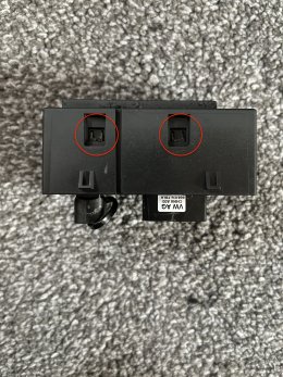
I want to route the USB cable from the module into the area under the armrest. I was thinking about replacing my existing AMI port with one of these that has the additional USB connector.

1624316744435
1624316824502


I was wondering, does anyone know if this can be disassembled so that I can replace the USB connector with the one from the CarPlay module? If not, does anyone know of any other ways for me to route the cable?

Thanks in advance!
 
It looks like the gold connector on the right is for the usb. The four pins would correspond to +5, gnd, d+ and d-.

Sent from my LM-V405 using Tapatalk
 
  • Like
Reactions: splinter-cell
  • Like
Reactions: raS3r and splinter-cell
I was incorrect in my earlier post. The usb port in this module is charge only so data pins would not be connected. I've also seen that the gold connector is present even without the usb socket.
That being said, I could see this being an easy hack to connect the the usb port pins to an external connector. You would need to open up the module though.

Sent from my LM-V405 using Tapatalk
 
  • Like
Reactions: splinter-cell
I was incorrect in my earlier post. The usb port in this module is charge only so data pins would not be connected. I've also seen that the gold connector is present even without the usb socket.
That being said, I could see this being an easy hack to connect the the usb port pins to an external connector. You would need to open up the module though.

Sent from my LM-V405 using Tapatalk
If thats the case he FAKRA HSD connector may be passing the USB data pins to the AMI connector which is why the USB socket is charge only, if this is the case to keep the AMI connector working you could just cut USB A socket off an extension cut the +and- 5v traces to the USB socket and drill a hole in the back and solder the extension to the connector.
 
  • Like
Reactions: splinter-cell
Thank you both for your in depth replies. I now have a better understanding of how it all fits together.
I think cutting the power pins from and extension and soldering it to the port might be the best course of action.
How difficult is it to take this module apart?
 
Have no
Thank you both for your in depth replies. I now have a better understanding of how it all fits together.
I think cutting the power pins from and extension and soldering it to the port might be the best course of action.
How difficult is it to take this module apart?
Sorry I have no idea, it looks like the module slides out from the back I'm sure it would pry out with a knife or a spudger. If you post pictures of both sides of the board when you get it apart I can probably tell you what's going on =)
 
  • Like
Reactions: splinter-cell
You can probably add a usb socket to your existing ami module rather than purchasing and modifying another.

Sent from my LM-V405 using Tapatalk
 
  • Like
Reactions: splinter-cell
Have no

Sorry I have no idea, it looks like the module slides out from the back I'm sure it would pry out with a knife or a spudger. If you post pictures of both sides of the board when you get it apart I can probably tell you what's going on =)
Ok no problem. I’ll PM you as soon as I get one.
You can probably add a usb socket to your existing ami module rather than purchasing and modifying another.

Sent from my LM-V405 using Tapatalk
Hmmm. I guess I would have to dremel the plastic to make a new hole?
 
Right, I’ve received the new AMI module but I have no idea what’s the best way to take it apart. Any suggestions?
F6E479A4 2C2D 4581 9B50 63B45F20E054
 

Attachments

  • DBC2E7E7-4BF8-46EF-95B4-46B53AEFEB12.jpeg
    DBC2E7E7-4BF8-46EF-95B4-46B53AEFEB12.jpeg
    1.8 MB · Views: 99
  • FA65B711-A630-4CDE-9A09-446BF886414E.jpeg
    FA65B711-A630-4CDE-9A09-446BF886414E.jpeg
    1.8 MB · Views: 84
  • C633B773-6E9F-46D6-B3DF-9E488F8CFFE0.jpeg
    C633B773-6E9F-46D6-B3DF-9E488F8CFFE0.jpeg
    1.7 MB · Views: 88
It looks like it comes a apart from the rear. You can see the two tabs on the bottom that need to be released. You should then be able to pullot the module.

Sent from my LM-V405 using Tapatalk
 
Trying everything I can but it just doesn’t seem to want to budge! Don’t suppose there’s a video or a guide out there?
Looks to me like the 2 clips I circled are the ones holding everything together, its unlikely there is glue.... it will all be fit by friction.
 

Attachments

  • DBC2E7E7-4BF8-46EF-95B4-46B53AEFEB12.jpeg
    DBC2E7E7-4BF8-46EF-95B4-46B53AEFEB12.jpeg
    1.9 MB · Views: 116
Looks to me like the 2 clips I circled are the ones holding everything together, its unlikely there is glue.... it will all be fit by friction.
On closer inspection, it seems like those 2 clips are the “wedge” type by which I mean they are set and have no flexibility to move at all.

I’ve bent the plastic housing around them slightly to disengage those two clips before I realised there’s also two hidden away on the other side. Again, I bent the plastic housing slightly to disengage those two clips too but the thing still doesn’t want to move
 
Sounds like there may be some more hidden clips.
As jrumball has suggested, try a butter knife between the parts (top, bottom sides) and see if you can see/release them

Sent from my LM-V405 using Tapatalk
 
  • Like
Reactions: splinter-cell
At this point, if you are still stuck, if you are carefull a heated scalpel blade will cut through the plastic like butter, as long as you don’t damage the face or the clips that hold it into the centre console you should be able to glue the insert back in in.

If you document what you find the next person won’t have the same issues =)
 
After ages trying, I finally managed to disassemble the module. I’m addition to the clips at the bottom, there are also a pair of clips hidden away inside the housing parallel to the clips that are visible. All 4 clips have to be disengaged at the same time and the you can wiggle the inner PCB out.
F1F38808 B778 4BBE 89A9 8C6360CAD732

Anyway, I have disassembled the inner module and this is what I can see. Any tips on the best way to approach this?
784E6944 886D 4D7C 87A1 8279E3DBB1A6
 
Remove the PCB and take 2 high quality photos of both sides of the board and post them back here. As discussed above the essence is to cut the traces to USB connector and solder your own cable onto the connector and route it out of the back of housing ….
 
Can you remove the circuit board from the plastic shroud and take close up pic of both sides of the board?
The usb connector will have 4 pins similar to attached pic - you may get away with just isolating the data pins and connecting those to the data wires of your cable. If this just a charge port they are likely not connected to anything already.

You could isolate (cut tracks on pcb) the four pins and then connect all your cable wires. V+ will be red wire, D- white, D+ green and gnd white.
62f8f8839d8d6bd6683d18d9b78444d4.jpg


Sent from my LM-V405 using Tapatalk
 
You will need to remove R33. Test if associated pins have resistance to surrounding components.
742da415d4ef4b41e554ce2c2466c728.jpg


Sent from my LM-V405 using Tapatalk
 
Can you redo this photo with more light in this area? Looking to identify any tracks.
If the two middle pins are open circuit (to other components) after removing R33, you should be able to connect your data wires to them.
ab2474e0068556936bb5f5337f078df8.jpg


Sent from my LM-V405 using Tapatalk
 
Can you redo this photo with more light in this area? Looking to identify any tracks.
If the two middle pins are open circuit (to other components) after removing R33, you should be able to connect your data wires to them.
ab2474e0068556936bb5f5337f078df8.jpg


Sent from my LM-V405 using Tapatalk
I’ll try and take some more photos later tonight.

So if I’m adding my own wires, does that mean I should remove the Fakra connector from the PCB and feed the power and data wires through the resulting gap?

Or would it be a case of still using the Fakra connector to provide power to the USB port, and just feeding the two data wires from an extension cable through some other hole, and soldering then on to the data pins?
 
Last edited:
I’ll try and take some more photos later tonight.

So if I’m adding my own wires, does that mean I should remove the Fakra connector from the PCB and feed the power and data wires through the resulting gap?

Or would it be a case of still using the Fakra connector to provide power to the USB port, and just feeding the two data wires from an extension cable through some other hole, and soldering then on to the data pins?
Need to do some more research here. It appears the fakra connector has a function (power/data??) related to the Ami. Did you want to disable that function?
Have a look here and see if you can fing the information. It's difficult to navigate on my phone.


As the fakra connector is different, ang you don't have a simple swap and play with these modules. I would be leaning towards just adding a usb socket to your existing module.

Sent from my LM-V405 using Tapatalk
No. I need the AMI port to be functional as the AUX output is what’s used by the CarPlay module to put out sound.

Yeah I know what you mean. This might be more complicated than I first thought. I’m tempted to modify the housing of the new module slightly so that it can accommodate my old modules PCB. Then I can just use the left over space from where the USB socket used to be to just wedge a USB extension in and feed the cable out of the hole for the Fakra connector.

I’m thinking something like this:
8AB65C33 0110 437F 83D3 278FE3A1805C

From the pictures I found, it seems like the PCB for the older module isn’t as wide as this one so hopefully should fit into the housing fine if I just cut the side a little.
 
Not a bad idea. Will be tight. I don't think you'll make it with the extra width of plastic moulding around the usb.

Sent from my LM-V405 using Tapatalk
 
edit: I'm slightly confused now, what does you car have in it at the moment ? I assumed you had bought another one of the same module to modify, not add a different module ?

If yo still want to keep the functionality of the AMI connector you will need to keep the Fakra I suspect the Fakra connector still passed the USB data to the AMI.

The ease way to test this is to disconnect the Fakra connector and see what functionality is left on the AMI connector.

If you want to Isolate the USB connector from the rest of the module you will need to remove the resistor between the middle pins, this shorting resistor tells the device the port is charge only, you could then solder the data lines to these 2 pads and then again cut the trades to +5v and solder your wires to the pads. Drill a hole in the rear of the housing and route the cable accordingly.... I don't think there should be any issues with not isolating the GND hopefully.

The other solution is like above to completely remove the USB connector and put an extension in its place, I think at that point you should ask why not just have the extension floating about. I have factory CarPlay and my phone lives in the cup holder so I don't forget to take it with me when I leave the car .......
AMI USB Passthrough


edit: I'm slightly confused now, what does you car have in it at the moment ? I assumed you had bought another one of the same module to modify, not add a different module ?

If yo still want to keep the functionality of the AMI connector you will need to keep the Fakra I suspect the Fakra connector still passed the USB data to the AMI.

The ease way to test this is to disconnect the Fakra connector and see what functionality is left on the AMI connector.

If you want to Isolate the USB connector from the rest of the module you will need to remove the resistor between the middle pins, this shorting resistor tells the device the port is charge only, you could then solder the data lines to these 2 pads and then again cut the trades to +5v and solder your wires to the pads. Drill a hole in the rear of the housing and route the cable accordingly.... I don't think there should be any issues with not isolating the GND hopefully.

The other solution is like above to completely remove the USB connector and put an extension in its place, I think at that point you should ask why not just have the extension floating about. I have factory CarPlay and my phone lives in the cup holder so I don't forget to take it with me when I leave the car .......
View attachment 239989


Sorry if I didn’t make it clear.

My car is a PFL A3 and it has just a single AMI port underneath the armrest. The new module that I have bought has the AMI and the USB Charge Only connector.

I have fitted a module from AliExpress that allows me to access CarPlay on my PFL A3 and I wanted to connect the USB port from the new AMI module to the USB port on the CarPlay module via an extension so I have a somewhat OEM looking way of using wired CarPlay without visible wires coming out from the glove box or near the cigarette lighter etc. The CarPlay module uses the AUX source to output sound so I have an AMI AUX adapter plugged in to the AMI port to make sure that the aux option is available on my MMI.
D7D08962 6E87 4BF6 AEF0 6FB2E93B95EB


It is only after reading the other guide that I realised that the Fakra connector in my existing module is different from the connector in the new module. I can’t sacrifice the AMI port as I still need a way to access the AUX source on my MMI.

This is why I decided to go down the route of transferring my existing AMI module into the new module’s housing and adding a USB extension in the left over space and then feeding the wire out of the back and to the CarPlay module.

You are right though, maybe I should test to see what the Fakra does before I go any further. If it stops the AMI port working then I may as well continue with the route I am on. Otherwise I guess I could give your way a go. Drilling a hole is way cleaner than modifying the housing lol. Thanks for the suggestion

I never noticed Q3 before. Any idea what it’s for?
 
Q3 is probably current regulation for the USB port, I suggest at this point your consider your aims, and the amount of effort you are prepared to put into having what looks like a factory install. You maybe much better off just drilling a hole for the cable and having a flying lead ...... or using something like the breakout board above.

As I said above I have never kept my phone in the arm rest when I use CarPlay it lives in the cupholder.......
Well, it was more work than it was worth but I eventually got what I wanted. I decided to go with @malteso original suggestion and dremelled a hole next to my existing AMI connector and glued a USB extension in place. I then fed the wire underneath the centre console, following the tracks of the factory wiring, fed it out into the dashboard area and connected it to the CarPly module.
 
Glad you
Well, it was more work than it was worth but I eventually got what I wanted. I decided to go with @malteso original suggestion and dremelled a hole next to my existing AMI connector and glued a USB extension in place. I then fed the wire underneath the centre console, following the tracks of the factory wiring, fed it out into the dashboard area and connected it to the CarPly module.
Glad you found a solution you’re happy with, half the fun of these modifications is in the process
 

Similar threads

Replies
2
Views
3K
Replies
14
Views
6K