Front Parking Sensors Retrofit - General Advice

q2us3r

Registered User
Joined
Mar 15, 2021
Messages
123
Reaction score
22
Points
18
Location
UK
Hi all,

Starting to read about this retrofit, the car already has factory fitted rear sensors. On paper it looks fairly straightforward but the devil is always in the details so I had a few questions:

1 - Where is the actual parking module located? Diagrams suggest that it's close to the fuse box, will removing the glove box give me access to the module? or does it require to remove more/other panels?

2 - Do all the plugs that go into the 4K module fit straight into the 8K module? how do the new sensors harness fit into the 8K module? through a new plug or adding new pins into an existing plug?

3 - How do you route the cables from the front bumper to the inside of the car, so to the parking module and to behind the new button panel?

Thanks!
1) above throttle pedal. suggest lower trims and glovebox be removed for this installation which will expose the module.

2) Yes. Existing sensors in lower connector, front sensors in upper.

3) Through the rubber grommets in the firewall and behind the dash. Kinda obvious once you remove the trims.

Thanks DJAlix, that is very helpful, thanks!

One further question that just popped into my head - I imagine the sensors needs to be connected in the correct order, so that the left/right sensors correspond to the left/right sensor images in the MMI. So when using a standard harness for the front sensors (OEM or from kufatec), the last connector in the harness, would that be for the most right sensor or most left sensor in the bumper?
 
if you are looking to complete this retrofit yourself then I would advise using a company which can supply a kit and indeed a guide in order to minimise issues. Sensor position depends on LHD or RHD and 3rd party looms are “sided”. Should always lay everything out and connect outside the car before installing to avoid issues.
 
  • Like
Reactions: JohnM100
if you are looking to complete this retrofit yourself then I would advise using a company which can supply a kit and indeed a guide in order to minimise issues. Sensor position depends on LHD or RHD and 3rd party looms are “sided”. Should always lay everything out and connect outside the car before installing to avoid issues.

Great advice thank-you, will do that. Otherwise it might just be the case of an obstacle to the left of the car and the MMI OPS display showing it to the right - I am sure I wouldn't have been the first person that would have happened too, sounds like it is bound to happen without proper preparation/checking first as you suggested.
 
1) above throttle pedal. suggest lower trims and glovebox be removed for this installation which will expose the module.

2) Yes. Existing sensors in lower connector, front sensors in upper.

3) Through the rubber grommets in the firewall and behind the dash. Kinda obvious once you remove the trims.
Removed the driver's lower dash trim this afternoon and the module is just where you said it was, on top of the throttle pedal, nice and clear access to it. Do you know where the bracket is that would hold the buzzer? is it around the parking module, so on the driver's side? or is it on the passengers side next to the fusebox/behind glovebox? (I have read contradictory information but could have been due to differences between RHD and LHD cars - I'm on a RHD car).
 
Removed the driver's lower dash trim this afternoon and the module is just where you said it was, on top of the throttle pedal, nice and clear access to it. Do you know where the bracket is that would hold the buzzer? is it around the parking module, so on the driver's side? or is it on the passengers side next to the fusebox/behind glovebox? (I have read contradictory information but could have been due to differences between RHD and LHD cars - I'm on a RHD car).
Buzzer is normally above the bonnet release handle
 
Hi q2us3r

I'm in the process of retrofitting front parking sensors to my FL A3, and I've reached the point of needing to access the existing 4 channel PCD module. From what you say it's necessary to remove the driver's lower dash trim. Can you explain how to do this please? Does it just clip in place, or are there screws etc?

TIA

Mike
One screw on the side and 2 M8 or 10 bolts under, rest is clipped.

But if you dont even manage to get this trim off I wouldn't continue this retrofit :blush:
 
Hi q2us3r

I'm in the process of retrofitting front parking sensors to my FL A3, and I've reached the point of needing to access the existing 4 channel PCD module. From what you say it's necessary to remove the driver's lower dash trim. Can you explain how to do this please? Does it just clip in place, or are there screws etc?

TIA

Mike

Exactly what henkkeumus said, one screw on the side (remove side panel first, it just pulls out) and two underneath - the rest are clips, you just pull it out (and disconnect the connectors to footwell lights, ODBII interface, etc to completely remove it). The 4K module is just on top of the throttle pedal but it's a little tricky to remove due to the annoying clips it uses to hold it in place...
 
  • Like
Reactions: Mikeso51
Exactly what henkkeumus said, one screw on the side (remove side panel first, it just pulls out) and two underneath - the rest are clips, you just pull it out (and disconnect the connectors to footwell lights, ODBII interface, etc to completely remove it). The 4K module is just on top of the throttle pedal but it's a little tricky to remove due to the annoying clips it uses to hold it in place...
Thanks, that really helpful. I could have worked it out by trial and error, but why risk breaking something? The
 
Just did this retrofit, works great.
In order to access the PDC/Buzzer location you need to remove the front trim around the steering wheel.

Remove the black "AIRBAG" plastic cover that's on the left of the steering wheel by prying it off using a plastic trim remover.

1628758235388


Remove this part using plastic trim remover, only tabs that's holding it it.

1628755627036


2. On a LHD car, driver side, remove 3 screws for front trim.

1628755701656

T10 torx I think.

One bolt here:

1628755793605


One here:

1628755874332

And then you should be able to pull it off towards you while sitting in the driver seat.
Make sure to disconnect the wiring for the headlight switch and the interior light without breaking the wires or connectors. They are held in pretty firmly so slight force might be required but everything after the point of removing the one bolt on the side and the two underneath, should be by pulling.

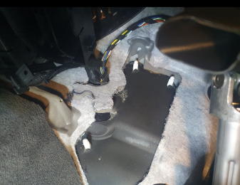
PDC and buzzer are fitted here, behind the fuse box:

1628755998440


PDC module will be quite obvious where it is when you look underneath since there should be a bracket if you have rear parking sensors (4k) since before. Buzzer was quite tricky to be found but there is a moulding for the buzzer that you can feel with your fingers on the backside of the fuse box.

Here's the PDC bracket holder that you simply pull out the red part and then pull down on the bracket and the PDC module should be free to be pulled down as well:

1628756232952


Here's my old 4k module that I removed:

1628756266456

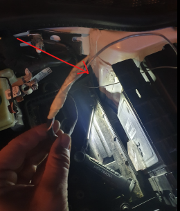
You should also see the OEM cable pass through in the firewall by locating this harness almost where the PDC module is located.
1628756362016


Wedge the red part of the foam away and you should see the pass through with a rubber gasket.

In order to access this pass through from the engine bay you need to remove the battery to expose the firewall and also the rubber grommet with the harness that you saw from the inside:
1628756571191


Audi were kind enough to incorporate a cable pass through (blue part) underneath the battery tray that you can ues to route the fron PDC harness so you can feed it through the firewall and connect it to your 8k module inside the cabin.

I used the nipple-looking part of the rubber grommet to pass through the new wiring so I didn't need to mess with the OEM harness.
Easiest way to feed the cable was to press the nipple so it appears on the inside, make a small incision and then start feeding some kind of wire that you locate in the engine bay, tape the front PDC harness to and start feeding into the cabin. Once the PDC wire has been feeded to the cabin, make sure to pull back on the wire from the engine bay so that the nipple goes back into it's original place and form. Depending on how small incision you made, you can tape off the rubber nipple and passthrough with some tape in order to be 100% sure that it's sealed so no water can get into the cabin.

Here's how it looked like after I was able to feed the wire inside the cabin.

1628756983040


After that it's just a matter of connecting the 6 wires to the T18 connector that is used for the front PDC and that goes into the 8k PDC module and connect the front buzzer (2 wires) to the already existing T26 conncetor that was previously connected to the old 4k module.
Connect the T26 and T18 connectors to the 8k module and put it into it's designated spot.

Before reassemblying everything, code the new 8k module and connect the parking sensors to see if they work.
I did my long coding using OBDEleven but people usually do the coding using VCDS.

After that the only thing that's left to do is to reassemble everything.

Btw. If you already have the 4k rear PDC like I did in my PFL 8V S3, replacing the button panel should be enough since it's already pre-wired to work with the new button panel for 8k PDC. Same thing with the CANBus High/Low so only modification you need to do is to add two wires to the existing T26 connector and assemble the new T18 connector that both go into the new 8k PDC Module.
 

Attachments

  • 1628756334293.png
    1628756334293.png
    4.7 MB · Views: 102
  • 1628756543817.png
    1628756543817.png
    3.9 MB · Views: 94
Last edited:
  • Like
Reactions: Bush_man
Just completed the same retrofit myself on my 2017 MY FL A3. UK car, so RHD.

Just wanted to say that the PCD module position can be one of two different places. In my car it was on the rhs above the accelerator pedal (as noted in the thread above). However it is clearly different in lhd cars, and someone else who carried out this retrofit on his rhd 2017 S3 saloon also found it on the lhs. I used a kit from AliExpress for my retrofit and the wiring loom supplied was clearly for a car with the PDC module on the left. This meant that it was about 30 inches too short to reach, and I had to extend it. Not a big deal, but something to be aware of if you are planning this mod.
 
Just about to attempt this (hopefully this weekend, just waiting for the loom to arrive) - could someone be able to share the VCDS coding? already have the back sensors, so only installing the front sensors. Thanks.
 
My coding for Park/steer module (10) is 05 30 05 10 01. This is for a 2017 MY manual car with no reversing camera.
 
My coding for Park/steer module (10) is 05 30 05 10 01. This is for a 2017 MY manual car with no reversing camera.
Thanks, that is helpful. I did imagine that this retrofit would probably just require small coding changes (if at all) - I guess the 8K module will probably already be set up (I bought it used so will hopefully be ready to go, I might need to turn the reversing camera option on as I have one of those installed). Did you install the option in the MMI to change the volume of the front sensors (like the option we already have for the back sensors) ?
 
Thanks, that is helpful. I did imagine that this retrofit would probably just require small coding changes (if at all) - I guess the 8K module will probably already be set up (I bought it used so will hopefully be ready to go, I might need to turn the reversing camera option on as I have one of those installed). Did you install the option in the MMI to change the volume of the front sensors (like the option we already have for the back sensors) ?
My PDC module came from a similar 2017 car, and I didn’t need to change anything in the code. It just worked first time, including the options in the MMI to change volume back and front, and enable/disable the auomatic operation.
 
My PDC module came from a similar 2017 car, and I didn’t need to change anything in the code. It just worked first time, including the options in the MMI to change volume back and front, and enable/disable the auomatic operation.

Ah that is very interesting, the MMI must have all those options turned on but show/hide them depending on the connected module. In the past I have always had to do some coding to 5F if I needed any new options enabled, but good to know that in this case they auto enable based on the installed hardware! Thanks.