HOW TO GUIDE – MTM M-Cantronic Tuning Box Fitting / installation guide – S3 8V model.
** THIS IS NOT AN INSTRUCTION MANUAL BUT A ROUGH GUIDE TO COMPLIMENT THE INSTRUCTIONS THAT MTM PROVIDE. IF YOU INSTALL YOURSELF FOLLOW AT YOUR OWN RISK. **
There has been a lot of talk on the forum concerning tuning of the S3 8V model and the pros and cons etc. This rough guide is not stating that the MTM box is better than any other option it’s simply one of the many routes that are available should you wish to add performance to your car. As part of that process some people consider the MTM tuning box. This product is however at the premium end of the price spectrum for the tuning box solutions, so what does your money buy?
Unlike other boxes, the MTM tuning box is fitted in line between the factory ECU and engine via the Can Bus system. It remaps the fuelling, ignition timing and boost pressure protocols. The M-Cantronic module increases performance and torque and reduces fuel consumption with an unchanged driving style. ( Other brand boxes dramatically change the character of the car, which some will deem as a pro or a con dependent upon personal taste ). The box comes with Audi heritage with the companies’ owner Roland Meyer having long historical links with Audi, having worked on the original Quattro turbo cars and tweaking Audi products since 1990 under the MTM brand. The MTM tuning box overall feels like a quality item with BOSCH OEM style connectors which are easy to install onto a car. The final point and for some the most important is that MTM are so confident in their product that they also offer a separate drive train warranty policy should Audi not honor the factory one.
Like others boxes, it of course offers performance gains whilst providing the ability to put the car back to stock for servicing and warranty work. In the case of the MTM box this process can be completed within minutes, which is a major advantage over other options which require owners to reach under the engine.
I noticed that there have been plenty of questions on the forum around the physical fitting of the device and what it actually looks like etc. So I thought I would put together some additional notes with photos and info gathered across the forums on what is involved in fitting the MTM M-Cantronic tuning box and hence people can make their own decision.
Quick points to note:
Thx to #nervous who found the following info:
MTM quote the following performance enhancements on their website for the European cars:
Stock: 300 PS Tuned: 355 PS
Stock Torque: 380 NM Tuned: 450 NM
Time required for home installation - Allow 10 minutes for 1st installation. Later ones should be between 2 – 5 minutes.
It might seem a little daunting at first removing the CAN Bus connectors but once you familiarize yourself with how they fit and where to place the excess wiring loom, fitting and removal of the device is incredibly easy and very quick. Of course if you purchase the MTM box new from a registered MTM dealer and they can install the device for you, the overall experience probably will include a dyno run, and scan of your car and a lot more hand holding. They say to allow 1.5 hours for this dealer process.
So here we go…..

What’s in the box that you receive?
1 X Translated instructions from German to English with black & white photos for reference.
1 X MTM M-Cantronic tuning box, complete with heavy duty OEM feeling wiring loom – The actual tuning box is small in size about 7 X 2 inches ( 5cm X 18cm ) in length.
2 X Double sided sticky strips for mounting the box.
1 X MTM Badge to place on the back of the car etc.

Tools / Items needed for the job:

Things to consider:
Ensure the engine is switched off and the keys are not in the ignition. Wait Approx 5 mins to ensure all systems are fully shut down.
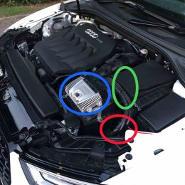
Fitting Details: - these presume you do not have the ECU cage to remove, or have already done so.
1) How to remove ECU from plastic cradle – Place your fingers over the edge of the top of the cradle and your thumbs on the back side of the curved part of the plastic cradle. Gently lever the plastic top edge of the cradle by bringing your fingers up whilst applying mild pressure to the back of the cradle with your thumbs. You can then start to slide the ECU unit out from cradle and then when partly out gently start to raise the ECU unit so that it completely frees the cradle. Take care with all of the connections and do not rush it. The first time you do this the wiring loom maybe very stiff. Also note which side you see facing you as you pull the ECU unit out of the cradle. It will only fit back in one way.


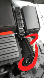
2) Removing existing CAN Bus connections – There are 2 connectors which are fitted to the ECU. In order to remove each one you need to pull the lever gently upwards. DO NOT FORCE THE CONNECTOR OFF. See Fig 1 below - As you pull the lever upwards and across the connector will automatically free itself from the unit. You may find that the lever is stiff first of all. Just close it down and gentle lift it up a few times slowly increasing how far you lift it up and across each time to free the mechanism. This is also where the can of WD40 used sparingly might come in handy. Fig 2 - By lifting up the lever you are releasing the locking mechanism which locks the connector in place on each plug. You will see it slide out from the side as you lift the lever. If you do not pull the lever in Fig 1 all the way up and across to its furthest position you will not release every one of the mini sliding locks and you risk damaging the unit / plug.

3) ECU Removal – Once you have taken both of the original connectors from the cars wiring loom out from the ECU you can safely place the ECU to one side. It should look something like this: NOTE that each side has a different set of pins therefore you have to marry the correct side up to each plug connector. In the picture below you can just make out the extra set of pins on the left hand connector ( right side of the left connector ).

The following picture shows the differences in each of the plugs that you have to marry up to the correct side on the ECU. When you come to fit, it’s pretty obvious.

4) Connect MTM loom to original wiring loom: You now have to connect the cars original wiring loom to the MTM female loom. Make sure you marry up the correct connector for each side. This should be pretty obvious. Gently place each connector into the correct slot. Then simply move the lever gently down into position. As you move the lever you will see the locking mechanism slide back in from the side and the connector drop down into the locked position.
5) Connect MTM loom to the ECU: Now with your ECU safely sitting to one side connect the MTM connectors to it. Just as above. To insert the connectors simply line them up ( making sure you have the correct side seated ) then move the lever gently down into position. As you move the lever you will see the locking mechanism slide back in from the side and the connector drop down into the locked position. DO NOT FORCE. Your wiring should now basically look like this:

6) Re-Sit ECU – You now need to re-sit the ECU back into the plastic cradle. In order to do this you have to ensure that the cars original wiring loom is gently moved as far out of the way as possible. You will probably need to hold it out of the way as you line up the ECU into the plastic cradle. You will have to slot it back in reverse order to how it was removed. I.e. at an angle then slowly lowered & slid back in. The finishing touch is to gently pry the cradle into the locked position over the top of the ECU.

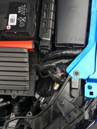
7) Tidy Cables - Now that the ECU is seated and locked into place you can gently push the cables into the spare space between the back of the light and the inside of the wing. If you want to make a neater flush job you might want to consider slacking off the air filter so that you can hide some of the excess cable under / around it. CAUTION: - Be careful of the small connector / relay that is on a flimsy bracket off the back of the headlight when pushing the excess MTM cabling into place. You can now slip the MTM M-Cantronic box in between the air box and battery. When finished your install should look something like this.


You may want to place some electrical tape / covering over the few exposed wires to protect from water ingress or external contamination. Example below.

8) You should be ready to go ! Once the box is installed there is no further adjustment. All calculations are carried out by the device in line with the ECU. There are no program adjustments available on the box as to the consumer it is a sealed device.
REMOVAL OF BOX. – This is simple, just reverse the above order. Should take you 2 – 5 minutes to put a car back to stock / standard form.
Final Notes:
1) Don’t forget the car should be run on 97 unleaded or better fuel not standard 95 unleaded for best performance once the box is fitted. This is basically the same/true as stock really.
2) Make sure you add the MTM box to your insurance. Obviously each insurance company and each person’s situation will be different.
3) Forums state that it is advisable to remove the box and wiring before any warranty/service work to avoid the TD1 flag issue which has become more prominent since March 2015. If you leave the device attached you do so at your own risk. (No users/ forums have so far reported a TD1 flag with the box etc fully removed from car)
And finally and most importantly after a safe install …. Enjoy your S3 and the improved performance the MTM M-Cantronic box offers!
** THIS IS NOT AN INSTRUCTION MANUAL BUT A ROUGH GUIDE TO COMPLIMENT THE INSTRUCTIONS THAT MTM PROVIDE. IF YOU INSTALL YOURSELF FOLLOW AT YOUR OWN RISK. **
There has been a lot of talk on the forum concerning tuning of the S3 8V model and the pros and cons etc. This rough guide is not stating that the MTM box is better than any other option it’s simply one of the many routes that are available should you wish to add performance to your car. As part of that process some people consider the MTM tuning box. This product is however at the premium end of the price spectrum for the tuning box solutions, so what does your money buy?
Unlike other boxes, the MTM tuning box is fitted in line between the factory ECU and engine via the Can Bus system. It remaps the fuelling, ignition timing and boost pressure protocols. The M-Cantronic module increases performance and torque and reduces fuel consumption with an unchanged driving style. ( Other brand boxes dramatically change the character of the car, which some will deem as a pro or a con dependent upon personal taste ). The box comes with Audi heritage with the companies’ owner Roland Meyer having long historical links with Audi, having worked on the original Quattro turbo cars and tweaking Audi products since 1990 under the MTM brand. The MTM tuning box overall feels like a quality item with BOSCH OEM style connectors which are easy to install onto a car. The final point and for some the most important is that MTM are so confident in their product that they also offer a separate drive train warranty policy should Audi not honor the factory one.
Like others boxes, it of course offers performance gains whilst providing the ability to put the car back to stock for servicing and warranty work. In the case of the MTM box this process can be completed within minutes, which is a major advantage over other options which require owners to reach under the engine.
I noticed that there have been plenty of questions on the forum around the physical fitting of the device and what it actually looks like etc. So I thought I would put together some additional notes with photos and info gathered across the forums on what is involved in fitting the MTM M-Cantronic tuning box and hence people can make their own decision.
Quick points to note:
- The full installation requires very little effort. HOWEVER - All of the DSG cars that I have viewed only have a plastic cradle holding the ECU – i.e. NO CAGE protecting the ECU. However manual cars appear more likely to have a cage fitted. If this is the case, removal of the cage is required to gain easy access to the ports. You may therefore need to factor in the removal and replacement of the sheer head bolts and the purchase of a new cage should you damage it as part of the removal process and want to put a caged car back to stock. This applies to S1, S3 etc.
Thx to #nervous who found the following info:
- ECU Cage item number - 5Q0907411B – Circa £21 ex vat
- Shear Bolts item number - N91146801 – Circa £1.10 each ex va
- Unlike other turning boxes. The MTM M-Cantronic box can easily be removed at the road side within minutes and in fact without the need to raise the car. For many this seals the deal.
- It’s been noted that the MTM M-Cantronic box removes the top end 155mph speed limiter. Although you are unlikely to be able to test this unless on the European Autobahn or on a private race track with a very long straight!
MTM quote the following performance enhancements on their website for the European cars:
Stock: 300 PS Tuned: 355 PS
Stock Torque: 380 NM Tuned: 450 NM
Time required for home installation - Allow 10 minutes for 1st installation. Later ones should be between 2 – 5 minutes.
It might seem a little daunting at first removing the CAN Bus connectors but once you familiarize yourself with how they fit and where to place the excess wiring loom, fitting and removal of the device is incredibly easy and very quick. Of course if you purchase the MTM box new from a registered MTM dealer and they can install the device for you, the overall experience probably will include a dyno run, and scan of your car and a lot more hand holding. They say to allow 1.5 hours for this dealer process.
So here we go…..
What’s in the box that you receive?
1 X Translated instructions from German to English with black & white photos for reference.
1 X MTM M-Cantronic tuning box, complete with heavy duty OEM feeling wiring loom – The actual tuning box is small in size about 7 X 2 inches ( 5cm X 18cm ) in length.
2 X Double sided sticky strips for mounting the box.
1 X MTM Badge to place on the back of the car etc.
Tools / Items needed for the job:
- Presuming you do not need to remove a cage , then basically nothing, although a can of WD40 used very sparingly might come in useful if the connectors are a little tight to remove.
Things to consider:
Ensure the engine is switched off and the keys are not in the ignition. Wait Approx 5 mins to ensure all systems are fully shut down.
Fitting Details: - these presume you do not have the ECU cage to remove, or have already done so.
1) How to remove ECU from plastic cradle – Place your fingers over the edge of the top of the cradle and your thumbs on the back side of the curved part of the plastic cradle. Gently lever the plastic top edge of the cradle by bringing your fingers up whilst applying mild pressure to the back of the cradle with your thumbs. You can then start to slide the ECU unit out from cradle and then when partly out gently start to raise the ECU unit so that it completely frees the cradle. Take care with all of the connections and do not rush it. The first time you do this the wiring loom maybe very stiff. Also note which side you see facing you as you pull the ECU unit out of the cradle. It will only fit back in one way.
2) Removing existing CAN Bus connections – There are 2 connectors which are fitted to the ECU. In order to remove each one you need to pull the lever gently upwards. DO NOT FORCE THE CONNECTOR OFF. See Fig 1 below - As you pull the lever upwards and across the connector will automatically free itself from the unit. You may find that the lever is stiff first of all. Just close it down and gentle lift it up a few times slowly increasing how far you lift it up and across each time to free the mechanism. This is also where the can of WD40 used sparingly might come in handy. Fig 2 - By lifting up the lever you are releasing the locking mechanism which locks the connector in place on each plug. You will see it slide out from the side as you lift the lever. If you do not pull the lever in Fig 1 all the way up and across to its furthest position you will not release every one of the mini sliding locks and you risk damaging the unit / plug.
3) ECU Removal – Once you have taken both of the original connectors from the cars wiring loom out from the ECU you can safely place the ECU to one side. It should look something like this: NOTE that each side has a different set of pins therefore you have to marry the correct side up to each plug connector. In the picture below you can just make out the extra set of pins on the left hand connector ( right side of the left connector ).
The following picture shows the differences in each of the plugs that you have to marry up to the correct side on the ECU. When you come to fit, it’s pretty obvious.
4) Connect MTM loom to original wiring loom: You now have to connect the cars original wiring loom to the MTM female loom. Make sure you marry up the correct connector for each side. This should be pretty obvious. Gently place each connector into the correct slot. Then simply move the lever gently down into position. As you move the lever you will see the locking mechanism slide back in from the side and the connector drop down into the locked position.
5) Connect MTM loom to the ECU: Now with your ECU safely sitting to one side connect the MTM connectors to it. Just as above. To insert the connectors simply line them up ( making sure you have the correct side seated ) then move the lever gently down into position. As you move the lever you will see the locking mechanism slide back in from the side and the connector drop down into the locked position. DO NOT FORCE. Your wiring should now basically look like this:
6) Re-Sit ECU – You now need to re-sit the ECU back into the plastic cradle. In order to do this you have to ensure that the cars original wiring loom is gently moved as far out of the way as possible. You will probably need to hold it out of the way as you line up the ECU into the plastic cradle. You will have to slot it back in reverse order to how it was removed. I.e. at an angle then slowly lowered & slid back in. The finishing touch is to gently pry the cradle into the locked position over the top of the ECU.
7) Tidy Cables - Now that the ECU is seated and locked into place you can gently push the cables into the spare space between the back of the light and the inside of the wing. If you want to make a neater flush job you might want to consider slacking off the air filter so that you can hide some of the excess cable under / around it. CAUTION: - Be careful of the small connector / relay that is on a flimsy bracket off the back of the headlight when pushing the excess MTM cabling into place. You can now slip the MTM M-Cantronic box in between the air box and battery. When finished your install should look something like this.
You may want to place some electrical tape / covering over the few exposed wires to protect from water ingress or external contamination. Example below.
8) You should be ready to go ! Once the box is installed there is no further adjustment. All calculations are carried out by the device in line with the ECU. There are no program adjustments available on the box as to the consumer it is a sealed device.
REMOVAL OF BOX. – This is simple, just reverse the above order. Should take you 2 – 5 minutes to put a car back to stock / standard form.
Final Notes:
1) Don’t forget the car should be run on 97 unleaded or better fuel not standard 95 unleaded for best performance once the box is fitted. This is basically the same/true as stock really.
2) Make sure you add the MTM box to your insurance. Obviously each insurance company and each person’s situation will be different.
3) Forums state that it is advisable to remove the box and wiring before any warranty/service work to avoid the TD1 flag issue which has become more prominent since March 2015. If you leave the device attached you do so at your own risk. (No users/ forums have so far reported a TD1 flag with the box etc fully removed from car)
And finally and most importantly after a safe install …. Enjoy your S3 and the improved performance the MTM M-Cantronic box offers!
Last edited:


 Absolutely, and to