I already have these built I'm but could do with them being brighter. Any recommendations on what bulbs to use?
You'll need to get hold of some LEDs.
I already have these built I'm but could do with them being brighter. Any recommendations on what bulbs to use?
Do you know what ones are compatible?You'll need to get hold of some LEDs.
Speak to t8ups, known on the forum for selling high quality lights.Do you know what ones are compatible?

Firstly please let me apologise if I'm stepping on anybodies toes here
I have come across a hopefully hassle free way to install Audi logo puddle lights, I know from previous comments, threads and forum's, people are wanting to install these but are somewhat put off due to the fact that in some cases it requires making / purchasing looms and then getting pins and connectors coded via vcds ect ect, which may incur a cost unless you know a friend of a friend.....you know what I mean.
But this sounds and is as witnessed working, a much simple way to install these love em or hate em marmite modification. I'm away to get mine fitted on Friday hopefully and pics will follow but here's how a friend of mine has overcome the loom, splicing, and vcds nightmare that has hampered so many people including myself
He has wired them directly into the central locking live and ground wires behind the door panels thus when door is open or unlocked via remote connection is made and logo lights. When vehicle is moving, after a few seconds the central locking auto locks the door and this in turn extinguishes the logo and likewise when you get out of the vehicle and shut the door and remotely lock it the puddle lights are turned off, so you can see is very much a simpler way to install puddle lights.
Im hoping this may prove helpful to people like myself who have had these for s considerable time and as yet have had them installed due to technical or ability issues
Regards Noz

Hi I am new to all this I am trying to fit door warning lights and puddle lights to my Q5 instead of the plastic reflectors I have wired all the lights up connected them to pins 16 front 12 rear does anyone know the codes and procedure to get them to work it is doing my head in : ( many thanksI'm not sure how splicing into the central locking wires is any easier than wiring into the correct points on the door module. I could imagine if you wanted to wire it without spending the extra couple of dollars on pre-terminated repair wires. But, why go to all the trouble to get the lights and connectors for the lights, and not get the crimp connection for the module side?
Did you get the door puddle/warning lights activated by vcds?Hi I am new to all this I am trying to fit door warning lights and puddle lights to my Q5 instead of the plastic reflectors I have wired all the lights up connected them to pins 16 front 12 rear does anyone know the codes and procedure to get them to work it is doing my head in : ( many thanks
No i have a mate of a mate who has a vag he said find the codes and he will change the codes over for meDid you get the door puddle/warning lights activated by vcds?
Module 52 and 42 for front passenger and driver door and i believe its +64 to the original value to activate. If its not +64 tell your mate when he opens the coding on each module and clicks on the current value a yellow balloon should pop up and in there it'll tell you the value to add on to activate the lights. Do this to the back doors too on their respective modules.No i have a mate of a mate who has a vag he said find the codes and he will change the codes over for me
Hi mate cheers for that so its the same code for Q5 as A4 he said something about needing the long code !!! thank youModule 52 and 42 for front passenger and driver door and i believe its +64 to the original value to activate. If its not +64 tell your mate when he opens the coding on each module and clicks on the current value a yellow balloon should pop up and in there it'll tell you the value to add on to activate the lights. Do this to the back doors too on their respective modules.

Hi Guys,
To confirm for 2005 A3 sportback the pins are:
Front -
Pin 18 = Live
Pin 19 = Ground
Rear -
Pin 1 = Live
Pin 2 = Ground.
I had a try at the door card removal earlier and it's a right nightmare. But at least I know how to take it off now...
Hi Guys,
To confirm for 2005 A3 sportback the pins are:
Front -
Pin 18 = Live
Pin 19 = Ground
Rear -
Pin 1 = Live
Pin 2 = Ground.
I had a try at the door card removal earlier and it's a right nightmare. But at least I know how to take it off now...

Incorrect.
These are only for 2007 onward cars.
All the pin number details are in this thread at the start.

Got a cancelled order so have the following available for immediate dispatch.
Front footwell kit - £32.50
Rear footwell kit - £50
Door kits - £36 per door
Postage (special delivery) £10
Prices include loom and lights.
Hi are you still doing the football lights and the puddle lights. Can you price for fitting plese
As promised in my post about DIY retro fitting footwell lights (http://www.audi-sport.net/vb/showthread.php?t=58215) here is my guide to fitting puddle lights and warning lights.
I fitted these this morning, took about 6 hrs in total for both doors.
You'll need VAG-COM to switch on the puddle and warning lights, i would advise you to do this first.
You'll need to go to 42 and 52 for the door electrics.

Then in the coding option you'll need to add '64' to the number you already have in the top box, mine was 0000560 so the final number needed was 0000624.
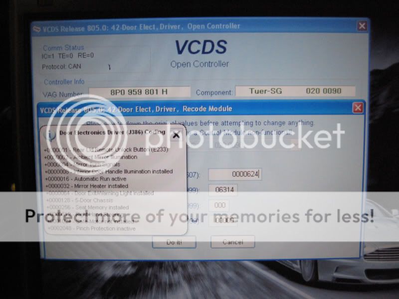
Do this on both 42 and 52.
This the vag com side sorted out.
Now for the hard work.
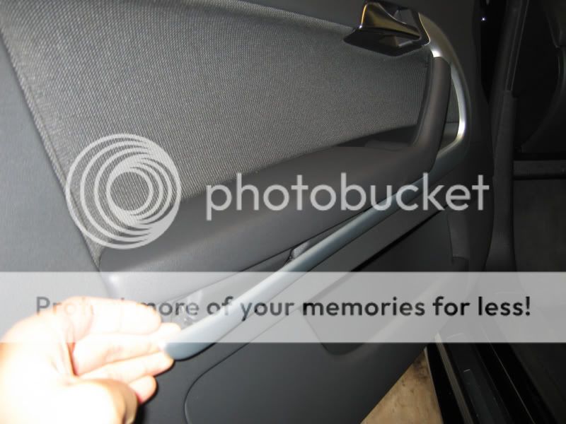
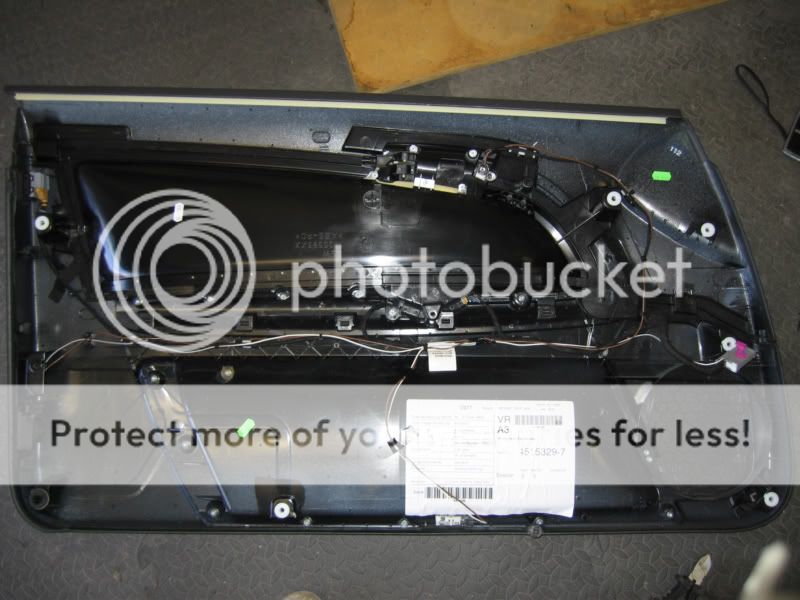
First of all the doorcards will need to be removed.
Remove the trim.

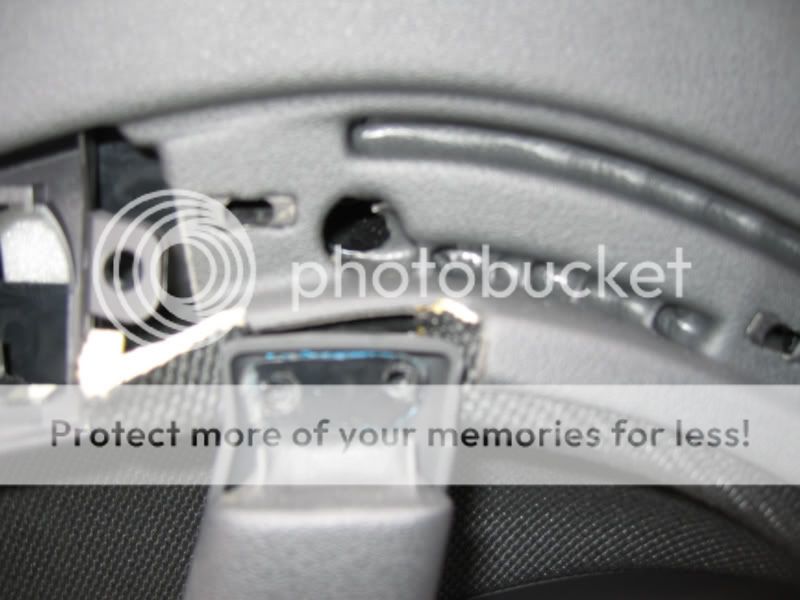
Undo the 3 screws holding on the door card.
Pull the door card off.
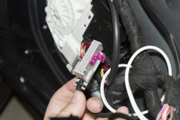
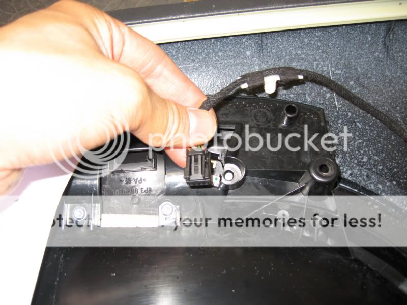
Undo the door handle cable and the electrical cable going to the door controller.
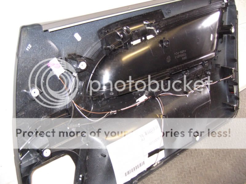
Remove the white foam stuff.
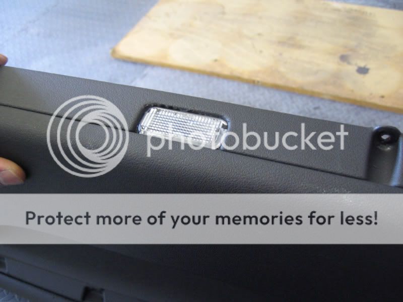
Now you'll need to remove some of the bottom of the door card for the light to sit in place.
I used a drill and used a small drill bit to drill around the rectangle.

Now the light can be palced into the hole, i used a tiny bit of superglue to keep the light in place.
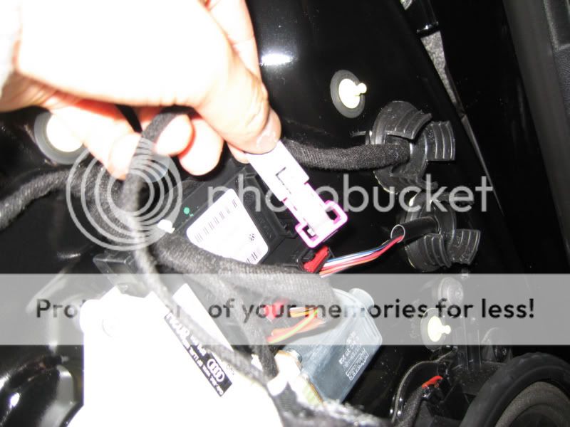
Now for the wiring - DRIVERS SIDE
You can wire the set up in different ways but this is the way i have done it.
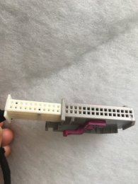
Remove the housing from the main connector (GREY).
Now pin 1 is the supply and pin 2 is the earth.
You'll need to get the supply wire to both the puddle light and the warning light.
I used one wire which then split off into 2.
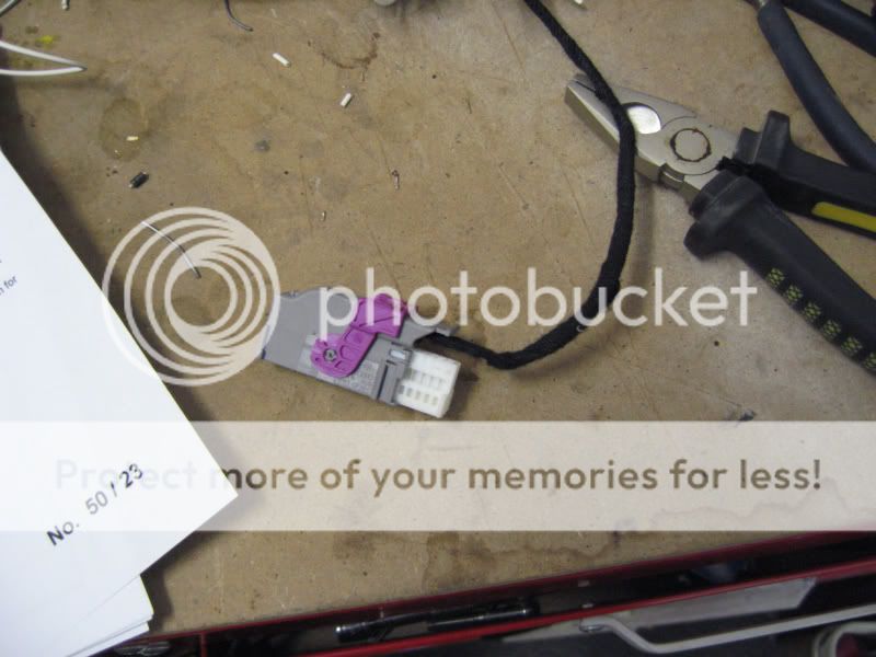
As for the earth this is the way i did it:
Unplug the connector going to the door lock switch.
Undo the clip from the connector by sliding it away.
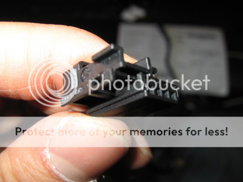
Remove pin 1.
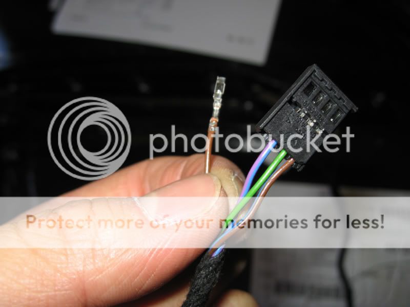
Replace this wire with another earth wire going from pin one to the earth on the warning light.
The wire which was removed from pin one must now be soldered onto the wire you just put in.
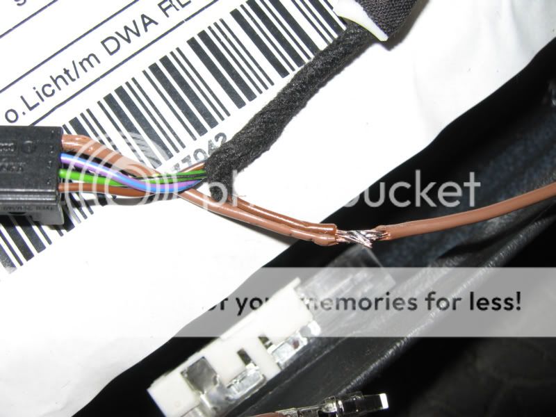
Now you must solder an earth cable going from the puddle light to the earth wire you have just put in.
Put the connector back and plug it back into the locking switch.
Now put the main grey connector back together.
This is what mine looked like when completed.
Put the door card back along with the door handle cable and electrical connector.
The lights should go on when the connector is plugged back in.
Now for the PASSENGER side
The same goes for the passenger side but there is no locking switch to mess with.
As with the drivers door grey plug needs to be taken apart, pin one is the feed and pin 2 is the earth.
Supply the lights with an earth and a supply just like the drivers side.
Remember to tie the wiring down so it doesn't rattle when the doorcard is back on.
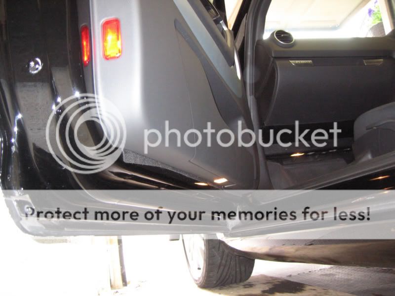
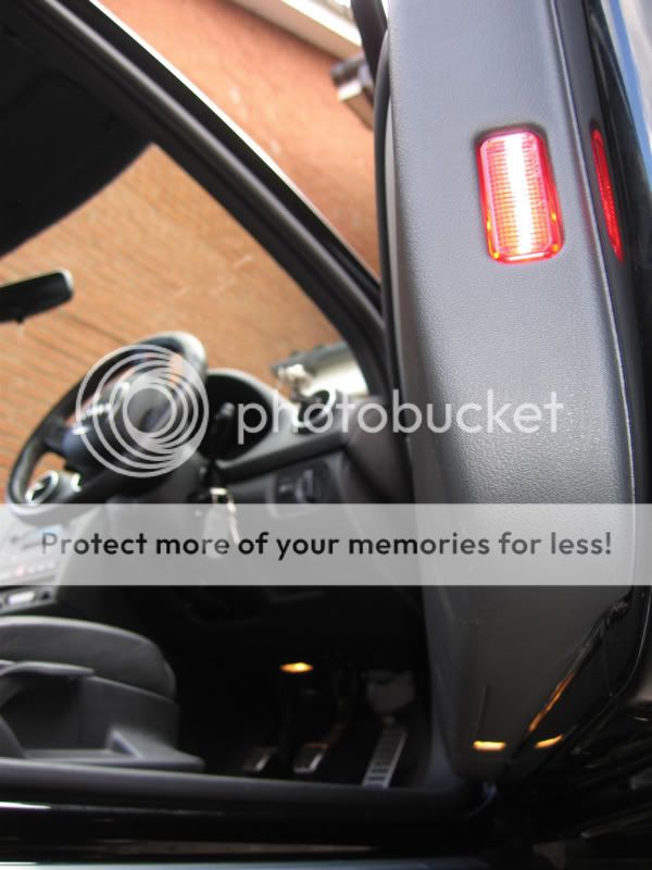
Put the door card back on and thats it really.
Here is the end result
If anyone needs any of the correct electrical connectors for the plugs etc then let me know as i have a supply of them.
Hope you find this post useful.
I have an Audi A3 sportback 2010 without factory fitted puddle lights. I want to fit a pair of logo lights to just the front doors. Which pins do I use on the 32 pin connector for live and earth connection.As promised in my post about DIY retro fitting footwell lights (http://www.audi-sport.net/vb/showthread.php?t=58215) here is my guide to fitting puddle lights and warning lights.
I fitted these this morning, took about 6 hrs in total for both doors.
You'll need VAG-COM to switch on the puddle and warning lights, i would advise you to do this first.
You'll need to go to 42 and 52 for the door electrics.
Then in the coding option you'll need to add '64' to the number you already have in the top box, mine was 0000560 so the final number needed was 0000624.
Do this on both 42 and 52.
This the vag com side sorted out.
Now for the hard work.
First of all the doorcards will need to be removed.
Remove the trim.
Undo the 3 screws holding on the door card.
Pull the door card off.
Undo the door handle cable and the electrical cable going to the door controller.
Remove the white foam stuff.
Now you'll need to remove some of the bottom of the door card for the light to sit in place.
I used a drill and used a small drill bit to drill around the rectangle.
Now the light can be palced into the hole, i used a tiny bit of superglue to keep the light in place.
Now for the wiring - DRIVERS SIDE
You can wire the set up in different ways but this is the way i have done it.
Remove the housing from the main connector (GREY).
Now pin 1 is the supply and pin 2 is the earth.
You'll need to get the supply wire to both the puddle light and the warning light.
I used one wire which then split off into 2.
As for the earth this is the way i did it:
Unplug the connector going to the door lock switch.
Undo the clip from the connector by sliding it away.
Remove pin 1.
Replace this wire with another earth wire going from pin one to the earth on the warning light.
The wire which was removed from pin one must now be soldered onto the wire you just put in.
Now you must solder an earth cable going from the puddle light to the earth wire you have just put in.
Put the connector back and plug it back into the locking switch.
Now put the main grey connector back together.
This is what mine looked like when completed.
Put the door card back along with the door handle cable and electrical connector.
The lights should go on when the connector is plugged back in.
Now for the PASSENGER side
The same goes for the passenger side but there is no locking switch to mess with.
As with the drivers door grey plug needs to be taken apart, pin one is the feed and pin 2 is the earth.
Supply the lights with an earth and a supply just like the drivers side.
Remember to tie the wiring down so it doesn't rattle when the doorcard is back on.
Put the door card back on and thats it really.
Here is the end result
If anyone needs any of the correct electrical connectors for the plugs etc then let me know as i have a supply of them.
Hope you find this post useful.
Some 2009 models are different. In the US for 2009, in front 18 is empty and 19 is already grounded so you have to splice into. in rear 1 is empty and 2 is grounded so you need to splice into 2. But for 2009 it should be the same 18/19 front and 1/2 rear.Hi which pins is it for an s3 8p 2009?


Some 2009 models are different. In the US for 2009, in front 18 is empty and 19 is already grounded so you have to splice into. in rear 1 is empty and 2 is grounded so you need to splice into 2. But for 2009 it should be the same 18/19 front and 1/2 rear.
The sockets are empty so there is no wire I have to make it stick, what is the name of the lugs I need to buy to make it fit?
Ok good one I did my front footwell I got the loom off ash.and wired into the socket pin 50.Right I’m looking to do this, think I might have an easier way but by all means shoot me down if it won’t work
I fitted footwell lights by tapping into the dome light and routing the cables
Now if I tap into that wire again and run a wire through to the door can I not just wire the lights to this extra cable
Hi is it the same for a3 8p sportback I'm just doing mines now back and front18/19 front
1/2 rear