Rear USB Dual Charger Retrofit

mulder85

New Member
Joined
Nov 5, 2020
Messages
16
Reaction score
1
Points
3
Location
Greece
Hello,

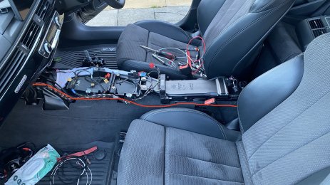
It looks like the face lifted B9.5 model has rear USB ports for the rear passengers, which is hosted on the back of the center console. As these are charge only and only seem to require power delivery, I was thinking perhaps it can also be done for the pre-facelift model?

However, I am not able to locate the part numbers. Does anyone have access to getting these part numbers required? I suppose we would need the the actual dual charger from existing implementations(5Q0035726L), but we would also need the new fascia for the rear-low facing part of the console, right? I could probably make the harness, but would still need to steal electricity from the rear cigarette lighter maybe?
 
Any luck finding the OEM pet number for this at all?

And the retrofit if you ever ended up doing it!
 
Ohhh…

Would you mind divulging these part numbers?

Let us know how it goes!


Sent from my iPhone using Tapatalk
 
If this isn't too expensive then I'm definitely interested.
Currently got a low profile 12v to dual USB but this would be much neater.
 
  • Like
Reactions: Exx-on
So....

It's a 2 to 2.5 hour job if you know what you're doing and have access to erWIN.

Firstly, tools:
  • Trim removal tools (plastic)
  • Torx screwdriver (various sizes)
  • Socket set (8 & 13mm) w/extention 3/8" & 1/4" are useful
  • Flat head screwdriver (small electrical type)
  • Long sticky thing
  • Mini blade fuse
Useful to have but not necessary:
  • Wire cutters
  • Wire strippers
  • Crimper
  • Fuse terminal (000979133E)
  • Harness tape
Obviously, don't forget https://www.kufatec.com/en/audi/a4/a4-b98w/complete-set-usb-hub-for-audi-a4-8w-43399

Note: The eBay seller failed to send me the instructions from Kufatec.

The trim & USB details are below:

49658A62 BBEF 4FED 81BD 30F5E5CE1562 1 201 a
1E9866AB 71BE 428E BE60 C8AA2A1FC262 1 201 a


The routing suggested is as follows:
Screenshot 2021 10 01 at 201519

Where I differed is that (2,3) for me terminated at the upper fuse box in the passenger side. It seemed more logical to me and I had already run a retrofitted rear camera here so I knew the layout and harness routings.

Here are some instructions and pictures to assist. I would urge you to review erWIN for positions of all components.

  • Remove the centre console
    • Remove trim pieces (14, 13, 12, 11, 15, 8, 18) - in this order (being mindful of all attached connectors)
    • The console is secured by 2 nuts at the rear, 2 bolts beside each front seat (covered by a plastic cover) and a single nut at the front
    • Unplug cupholder connector near start/stop button
    • Unplug any wiring located in your arm rest area (USB/AUX/charging)
    • Lift arm rest up and remove air vent plastic (watch out for connector)
    • Pull from the rear in an upward and rearward direction - untangle the connectors as it moves, it should have no resistance - it'll easily remove from the rear doors
Screenshot 2021 10 01 at 202745

  • Remove glove box
    • Remove side panel (not shown)
    • Unbolt all 9 bolts (this glovebox is not moving otherwise)
    • Being careful of the wiring/ventilation at the rear, unplug and tuck the glovebox away for later
Screenshot 2021 10 01 at 202841

  • Start laying wiring harness, starting at the rear and making sure you leave some slack
    • Routing follows the "transmission tunnel" under the carpet where possible (long sticky thing is useful here) and up into the dash
      • See picture (red line)
    • Use harness tape to secure the routing and make it look OEM
    • Once you've tucked this up into the centre console you can route it up over the MMI unit and over to the fuse box
      • Use harness tape to secure to dashboard area (the main harness is tucked too far inside the dashboard to route with the harness)
    • Secure the fuse terminal into the fuse box. I found an empty fuse slot and added the harness into it (my harness was too long so I cut it to size and used the a new fuse terminal)
    • The grounding spot can be anywhere with uncoated structure near the fuse box (if you make your own harness or fancy stripping the harness tape off the supplied harness, you can ground it at the red dot)
    • Install fuse into holder, I used 10 amp
IMG 8532 1


  • Last steps are to fit the new trim into the rear vent panel
    • Removing the 12v socket is a pain and requires a flathead screw driver and steady hands
      • This video may help
    • The trim piece is secured by two plastic tabs and requires a little force to remove
    • Now fit the 12v socket into the new trim piece (take note of the keyway)
  • Now you're ready to refit everything and test it out
    • Hint - refit is the reverse of removal
IMG 8538


I hope this helps someone!
 

Attachments

  • IMG_8532 (1).jpeg
    IMG_8532 (1).jpeg
    1.6 MB · Views: 192
  • Like
Reactions: ub7rm and mulder85