TQS track car project - extremely slow progress

Thanks. Found an adapter which can be welded on to my current fmic pipework.

I'm struggling to find AWT wiring diagrams for the white ecu plug and brake /clutch switches. Found one for AWM, but it has different wire colours and isn't complete.
My elsawin doesn't have the diagrams :(

Also, do you guys know if the wideband o2 sensor fits straight in instead of our stock one ? I assume the rear one will have to be coded out?

Also, not sure what is needed to have the vvt working.

Any help would be appreciated. I want to sort out the wiring before I start stripping dash to remove peddle box.
@aragorn @Bradderz_1988 @Broken Byzan
you dont need to remove the dash to do the peddle box, but he master cylinder and servo need to be pulled.

The peddle loom is easy enough, i'll try and find a diagram in elsa. just use pin numbers over colours if confused
 
  • Like
Reactions: slepy
The passat that I got it from had cruise, which I won't be fitting. I assume that it has additional wires on the switches which I won't have to connect. Ordered full elsawin on ebay 2 weeks ago and still didn't get it.
 
Just had the 5 speed and diff delivered and I'm glad I changed my mind about swapping 6 speed in. The difference in weight between the two is massive. Yesterday two of us could barely carry the 6 speed and today I managed the 5 speed myself.
 
My mate is just getting used to the maintenance costs on his S4 after needing the box and diff in space off a month lol

This cold weather is doing my head in cant get nothing done on the B5 still need to pull the carpet out to get it cleaned and pull the block aswell.
 
My mate is just getting used to the maintenance costs on his S4 after needing the box and diff in space off a month lol

This cold weather is doing my head in cant get nothing done on the B5 still need to pull the carpet out to get it cleaned and pull the block aswell.
Yeah, he picked up the box yesterday. Not ideal having to fork out for both, but perfect timing for me, as it paid for the 5 speed ;)
 
Managed to get some AWT wiring diagrams but I can't find ones for the other ECU plugs.
Want to compare the pins in all plugs between AJL and AWT.
I think it will be a matter of going through every ECU related diagram to find all pins. But first need to get all the diagrams.
Obviously the white plug is a different story, as it doesn't exist in AJL.

Can you have a look at this and let me know if my thinking is correct?:
Brake switch:
1. Pin 2 goes to pin11 on white plug.
2. Pin 4 goes to pin 12 on white plug
3. Pin 1 goes to fuse 13. I believe the AJL brake switch should have the same wire going to the fuse. So it is a matter of
cutting it off and soldering the new one.
4. Pin 3 needs to be connected to positive from somewhere. On the diagram it says "Positive connection 2 (15), in dash panel wiring harness" but god knows where it is.

Clutch switch:
1. Pin 2 goes to pin 13 on white plug.
2. Pin 1 needs positive. Same as Pin 3 on the brake switch.


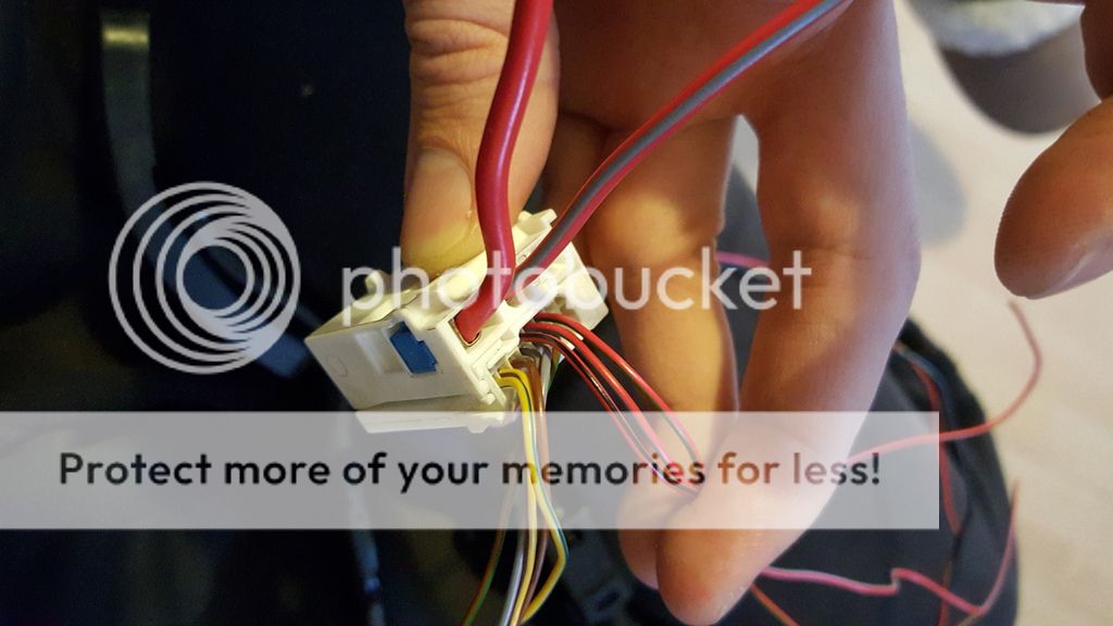
I can't find anywhere where the two thick wires from white plug should go.
All diagrams describe this plug as 15 pin. But it is 15 pins of only the thin wires.
The red wires are clutch/brake switch wires. The rest of the thin ones are for accelerator.
 
Yeah. Trying to find any diagrams with the other half but no luck so far.
 
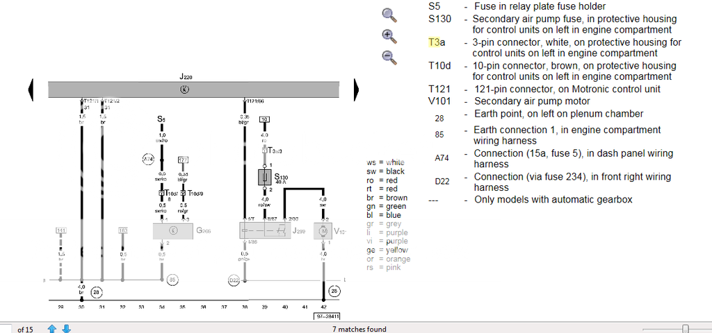
Found white plug on the diagram below, but am I thinking correctly that it is on the other side of the plug?
This relay and fuse are both on the engine loom. Same as on the diagram you posted?

And when I trace the track "10", it shows it goes to screw connection 1 (30) on relay plate.
 
Last edited:
yeah that looks right, so perm live from fuse box post.

This is car side of the plug, not engine side by the looks, IIRC i had mine use the perm live from the OEM brake light switch as you effectivelly end up with 2 switches on the brake peddle on the DBW setup in one actual switch, both of which need to run back to the ecu

The S130 fuse and J299 relay are both in "protective housing for control units on left in engine compartment", together with the ECU.
That's one of the only two fuses and relays that sit together with the ecu? Right?
If that's the case, the diagram must be showing the other side of the plug.
The track 10 would be the one going to the inside of the car, to the screw connection 1 (30) on relay plate
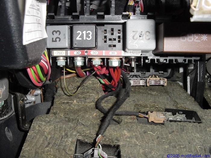
Which should be one of these where all the red wires go to?
elec130_DSC00625.jpg


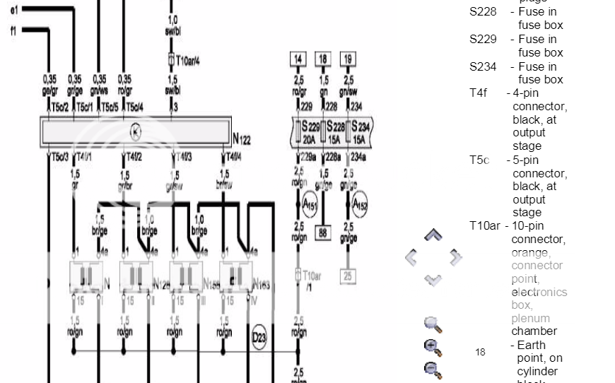
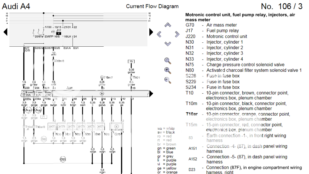
When it comes to the red/grey wire, I can't find anything on elsawin for AWT, but the one you posted has it going to fuse S229 20A (track 14 on diagram 4/8). Question is, is there anything now on this fuse in our cars?


The one on page 4/3 is the other side of the plug going towards the relay in the ecu box.
 
Ok, Pretty much worked out all the internal wiring except for one thing.

The red/grey wire from white plug needs to go to fuse 229.
The opposite pin of this fuse, on AWT ,is a red/green wire which goes to pin 1 on the orange ecu plug.
(As seen on the two diagrams above)

The AJL diagram below shows that the red/green wire on the fuse 229 is the same, and goes to the same location on orange ecu plug.
But, the opposite side of the fuse is connected to the 87F/Diesel under the relays, as there is no white plug obviously..

SO the question I have is, do I plug the red/grey wire to the fuse instead of the 87F connected wire?
And disconnect the 87F wire completely?
I assume that the red/grey wire will supply power to the orange plug, instead of getting it from 87F connection under the relays.
Please advise @Broken Byzan @aragorn
 
Just realised that, according to diagrams, the brown and red plugs have completely different pins/wires connected.
Might take me few weeks to work it all out lol
 
Hmm, this is from memory:

There are 3 or 4 large wires, which are all the main power feeds for the engine.

On the AJL, The fuel pump relay hangs directly off the main 12v bus in central electrics, and then the feeds come out of the relay, into their respective fuses, and then on to the various circuits thru the red/brown plugs etc.

On the DBW cars, the fuel pump relay is powered by a relay in the ECU box, so on those cars, the car sends a 12v feed up to the relay box on the white plug, then sends it back down to the relay panel/fuse box etc, before then doing the same as the AJL.

You can fairly easily tweak the wiring back so its the same as the AJL version, rather than trying to replicate what the DBW harness does.

The three power feeds are also swapped about a bit between the two looms. You can either move the DBW's wires to match, or just ignore it as they all come from the same place anyway.

Again, from memory, the brown and red plugs are all directly compatible.

I sat down yonks ago and went thru the whole harness diagrams, and mapped out every pin on both. I'll see if i can find my notes.
 
Oh and from memory, none of those fuel pump relay outputs connect to the studs underneath, theres a big multiplug on the back of the housing that everything connects to.
 
  • Like
Reactions: slepy
The problem I've got, is that I can't find all the pins on diagrams. Pretty much all the pins on red plug I could find, are different on awt to ajl.

So with the power wires, it would be possible to leave the red/grey wire that feeds orange plug alone, and leave it feeding from 87F? And check if it is the same for the other power wires in all plugs.
 
I had to add ignition feed to one corner of a plug that was not powered by the car to power the ecu up. That was it bar the white plug. I also added the Mil and epc feeds to the dash. Ps early tqs dashes have no led on board for the mil lamp
 
I had to add ignition feed to one corner of a plug that was not powered by the car to power the ecu up. That was it bar the white plug. I also added the Mil and epc feeds to the dash. Ps early tqs dashes have no led on board for the mil lamp

Which plug was the power feed for?
Did you have to change around a lot of pins in other plugs? My red and brown seem to have different pins used on ajl compared to awt. Didn't have a chance to look into them yet as work is hectic.
 
Did you use the APU loom?
 
Need to get the loom out of the ECU on the car and compare it with the AWT loom, to make sure my diagrams are correct.
 
I'm worried myself mate. Can't find the complete awt loom diagrams to compare all the pins, but what I managed to find didn't look like a straight swap at all. At least red and brown plugs.
 
will try and find some time to dig out my AWT harness and see whats what.

Also i'll get the part number off it and compare it with yours.
 
  • Like
Reactions: slepy
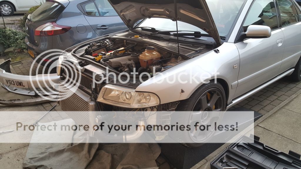
Was planning to go to UD2016 yesterday, but because it was a first day with nice weather and decent temps, I've decided to fit the engine and box mounts.
Car went on ramps. Service position in 10 minutes.

Nothing is ever simple on this car. Fitted all the mounts and started tightening all bolts. Engine mounts and one box mount went all ok. Second mount, last bolt and it snaps! Had to pull it out and drill out the bolt.
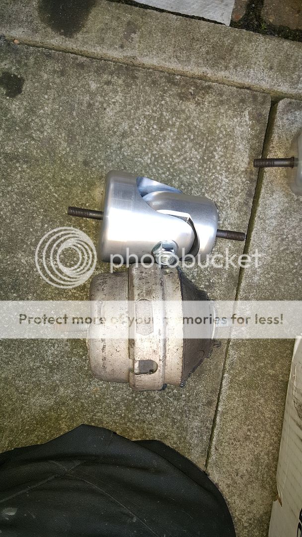
Engine mounts before and after

****** hell it is now ridiculous inside. The vibration and noise are shocking - feels like a race car! Not something for a daily driver!

Didn't fit the snub mount, because looking at it, it won't fit.
Will do the diff mount when I swap diffs.
 
i did suspect those mounts would be somewhat overkill. Is there a polybush or something inside the pivot on the alloy part, or is it totally solid?
 
Yeah there is rubber. Not really bothered about the noise because it is a track car after all, but exhaust ****** me off. Still touching somewhere.
 
Booked a track day at Cadwell on 22nd of May. £169 for a full day on Javelin trackdays.
Need to do few jobs before then:
- buy longer wheel bolts for rear
- roll front arches and prime/paint underneath as the pain is coming off
- fit new fuel filter ( which I have for over a year now!)
- fit the diff I bought with changed oil
- fit diff mount
- check the driver's seat as it is making some cracking noise after mallory
- check pad wear sensor wiring - had light coming up after 10-15 hard laps ( fluid was ok).
- check the ****** exhaust mounts again to see where it is catching now
- brake cooling ducts if I have enough time
 
I was looking at those 034 mounts myself and wad wondering how they'd be in use. Think I may just fit a pair of stock S4 mounts if they're any different
 
compared the B5 2001 AWT harness with the 2000 AJL harness today on Elsawin.

They are more or less identical.

As mentioned earlier, a few small tweaks are required to the orange plug to add an ignition live.

What AWT loom do you have? Should have a part number on a white tag?

I'm going to confirm my diagram physically matches the harness tomorrow, then i'll document the tweaks required to the orange plug.
 
That would be great. I will finally have time this weekend to have a look inside the ecu to compare the plugs as well. Couldn't find any tags on the loom, but was comparing awt wiring diagram with ajl and they were different on red and brown plug. Orange is pretty much the same just needs the power wire adjusting.
 
Can you take couple of pics of your awt plugs @aragorn ?
 
my black and brown are identical, bar the brown having engine management light...

Did you maybe pick the 1998 variant of the AJL loom rather than the 99? Thats quite different.

I'll get some photos and list the wire specs tomorrow.
 
I had only one ajl loom on my alsawin