SweatySweater
Registered User
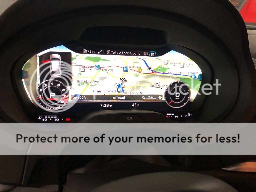
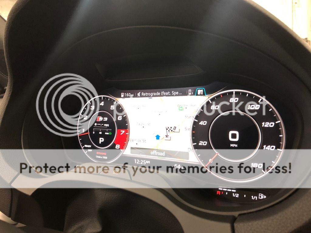
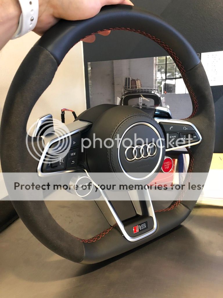
I am attempting to retrofit a MK3 TTRS steering wheel, with FULL functionality into my Pre Face Lift, S3 8V. This is just the beginning of what will be a full retrofit of the Virtual Cockpit and MIB2 system with CarPlay enabled.
The updated steering wheel is necessary to have access to the "VIEW" button, to change display settings on the VC.
I will pre-face this by saying that I haven't found another thread with a car in the US, that has been capable of retrofitting the VC, or even attempted. I know there are a few guys in EU that have done this, and now MK7 Active Display retrofits are popping up here in the US as well. I have seen a couple of people that have retrofitted the TTRS wheel into the MQB cars with only partial functions. I am hoping that we can have the wheel work 100%.
My first challenge was to find a MIB2 Unit that could have NAR maps installed, and them work correctly, and also have CarPlay. Sirius and DAB (Digital Radio) aren't really a huge concern of mine. I created a list of part numbers of MIB2 units from US MQB cars with Parts Link. Unfortunately with it only being around for a couple of years so far, the cheapest NAR MIB2 unit I could find was still $4k +. This simply is not an option due to the total cost that the project would come to. After speaking with multiple companies over sea, I ended up working with APG in Poland who specializes in retrofitting MIB/Clusters.
They say they are able to source me a MIB2 unit, with NAR maps installed, CarPlay enabled, Sirius, and DAB. For those not familiar, Audi and VW now uses SwaP codes to unlock these features on cars that wish to upgrade. After researching, even though my S3 came with NAV, it is not the Google Maps style of Nav on the new cars. My VIN also isn't eligible for the CarPlay FEC code due to it not being available during my production or MIB1. It seemed as though my only option was to get an unlocked unit.
And here we are, at the beginning of this long road. I will say again, I am not sure that the VC will work 100% but I want to get it as close as possible and have this serve as the guide to help people who wish to do this in the future.
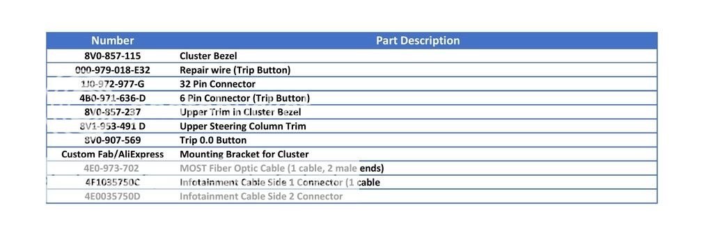
Parts that have been ordered so far:
-TTRS Steering wheel with airbag and harness
-LCD Instrument Cluster: 8V0-920-790-A
-MIB 2 Unit: 8V1-035-035 (There are multiple part numbers for this, depending on features and it is region specific)
-LCD Trim: 8V0-857-115
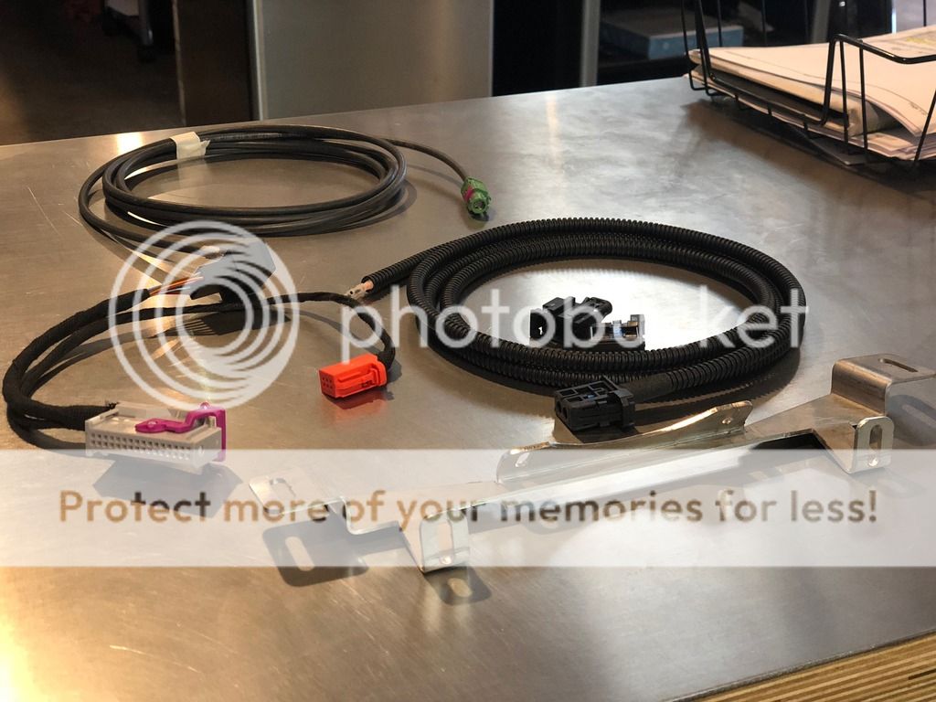
-HSD and MOST cables to run from the back of the MIB2 to the LCD
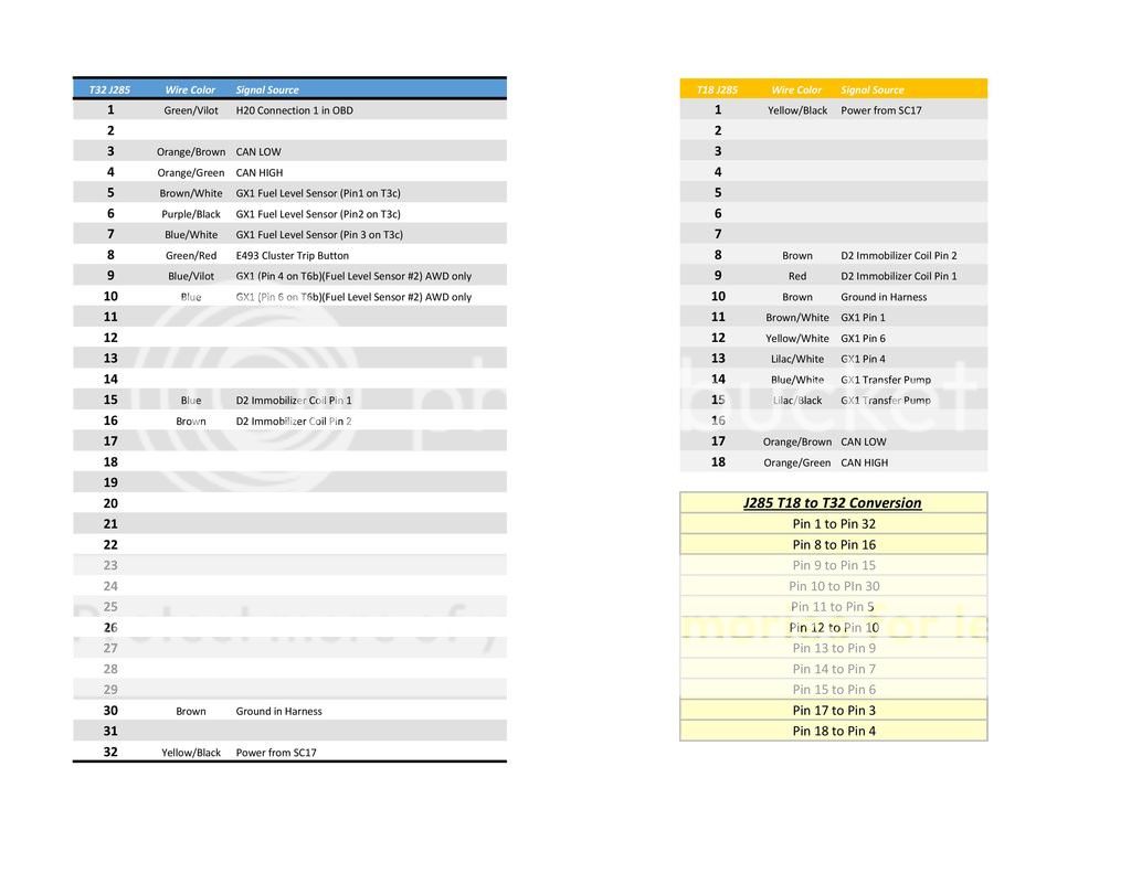
-Adapter harness for Cluster (Original is 18 pin, new cluster is 32 pin)
-Bracket for mounting LCD
-USB port for CarPlay and wiring
While we wait for the VC parts to arrive, the steering wheel needs to be installed.
Plug and play does work with the new steering wheel. The airbag connectors are different, but can easily be swapped. Both airbags are however, 1 stage airbags.
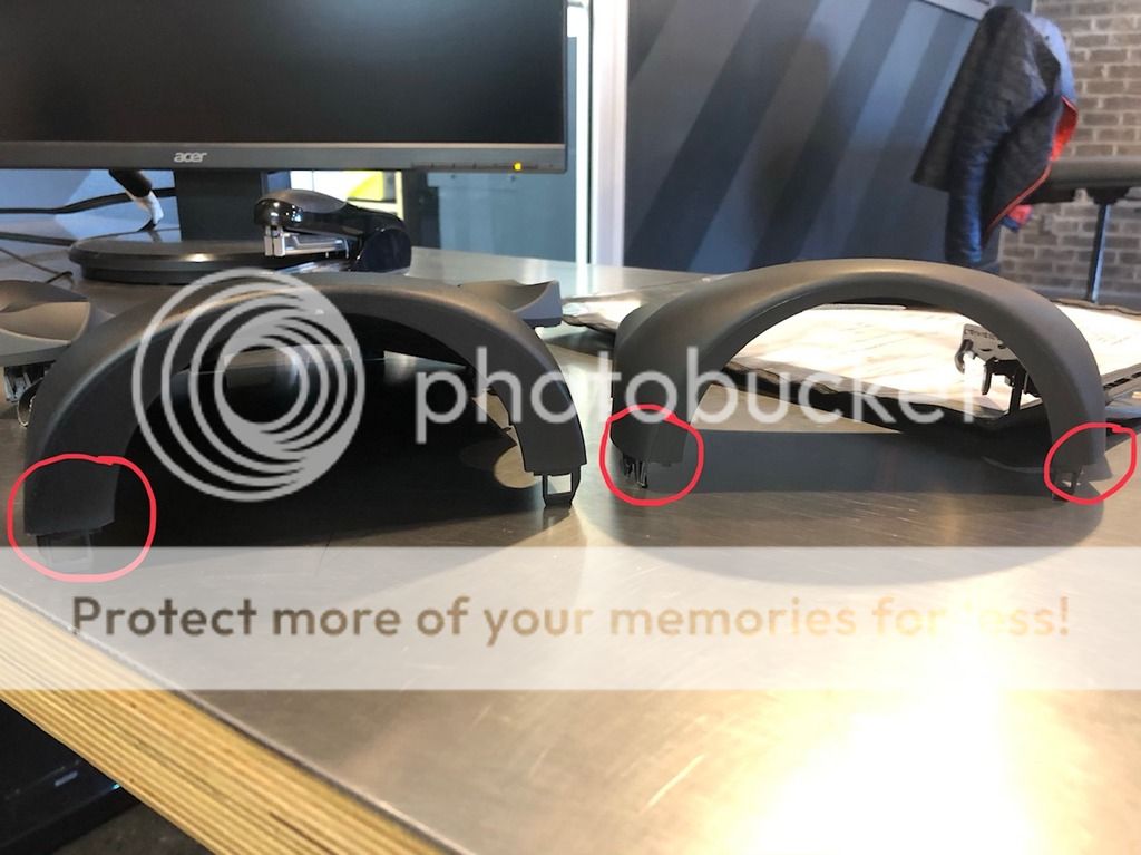
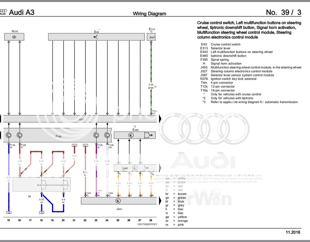
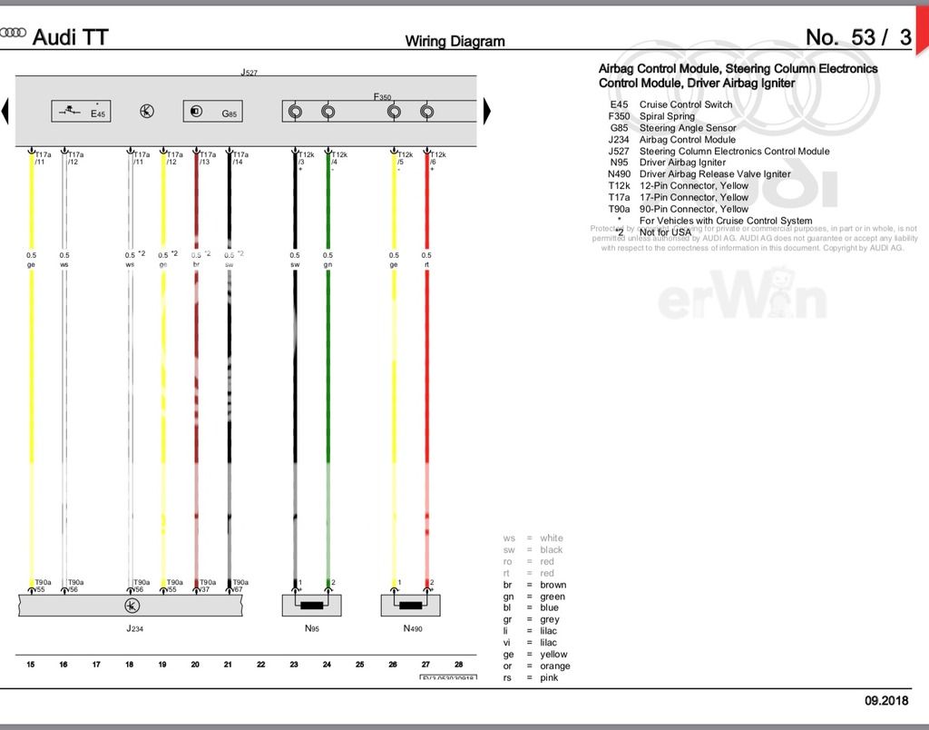
Here is where I ask for the first bit of help. The S3/A3 has a clockspring F350, separate from the the Steering Column Control Module J527. The TTRS using a 1 piece design that houses the clockspring, wiper stalk, and cruise control stalk. Here is the wiring layout for the yellow 12 pin connector on the clockspring from both steering wheels.
S3:
Pin 1:
Pin 2:
Pin 3: Black wire, Ground for N95 Igniter
Pin 4: Green wire, Power for N95 Igniter
Pin 5:
Pin 6:
Pin 7: Brown wire, Ground Connection that also goes to the Horn, and pin 3 of T4 connector on steering wheel.
Pin 8: Blue wire, Power for horn function, constant B+
Pin 9: Purple wire, LIN Bus, goes to Pin 1 of T4 on steering wheel.
Pin 10: White wire, constant B+ for steering wheel, goes to Pin 2 of T4 on steering wheel.
Pin 11: (Has pin on Clockspring, but no wire from steering wheel)
Pin 12:
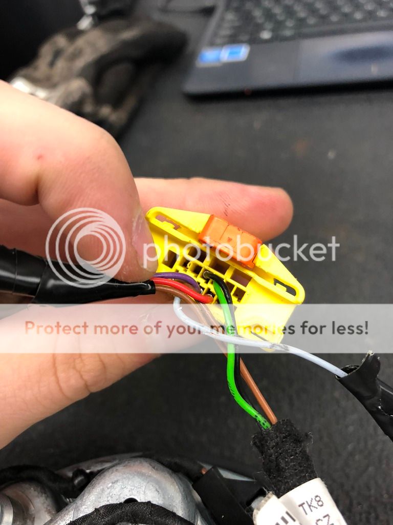
TTRS:
Pin 1: Gray wire, goes to Pin 2 of T4 connector for Start/Stop and Drive Select Buttons (Unknown Function)
Pin 2: Light gray wire, goes to Pin 1 of T4 connector for Start/Stop and Drive Select Buttons (Unknown Function)
Pin 3: Black wire, Ground for N95 Igniter
Pin 4: Green wire, Power for N95 Igniter
Pin 5:
Pin 6:
Pin 7:
Pin 8: Brown wire, Ground Connection that also goes to the Horn, and pin 3 of T6 connector on steering wheel.
Pin 9: Purple wire, LIN Bus, goes to Pin 1 of T6 on steering wheel.
Pin 10: Red wire, constant B+ for steering wheel, goes to Pin 2 of T6 on steering wheel.
Pin 11: Gray w/ Red Stripe wire, goes to Pin 3 of T4 connector for Start/Stop and Drive Select Buttons
Pin 12:
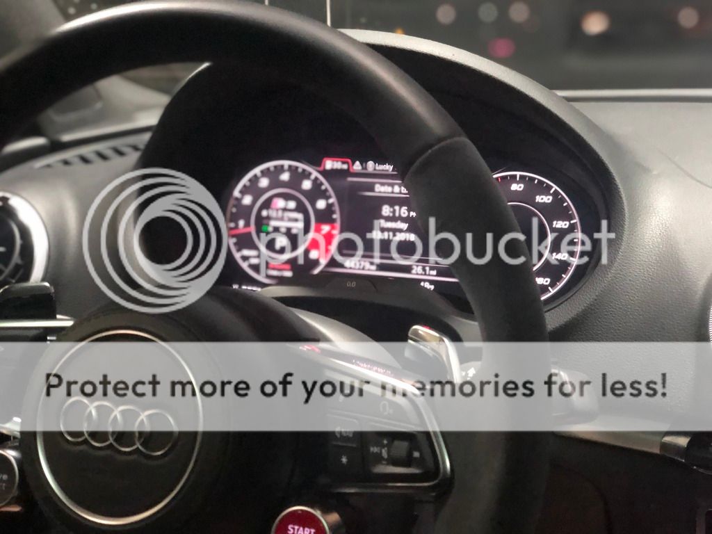
I was able to get basic functions working on the wheel. 80% of the buttons, the lights, and the horn.
Using the harness from the TTRS wheel:
Move the brown wire from Pin 8 to Pin 7. Its that simple.
This gives you Purple, Red, and Brown on the T6 Connector at the top of the wheel. This provides all the basic functions.
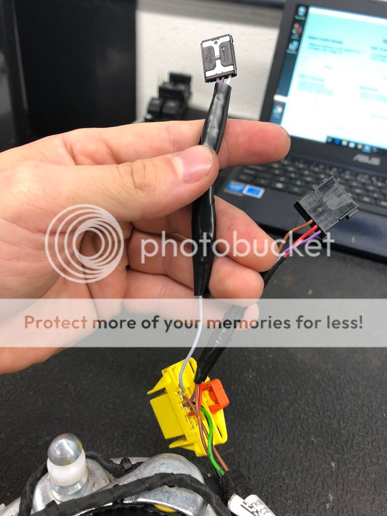
The wheel has a T4 connector with 3 wires for the Start/ Stop and Drive select Buttons. Only 3 wires. The S3 clockspring only has 2 remaining pins though.
Pin 8, and Pin 11. Both of which have B+ when the key is on, and again, I am left with 3 wires for those two buttons.
Are these wires Power, Ground, and LIN?
Signal, signal, and ground?
The wiring diagram is very vague and only has the wires listed as black. No colors are listed. Another fun fact, is the Start/Stop button currently also activates the horn :thumbs:
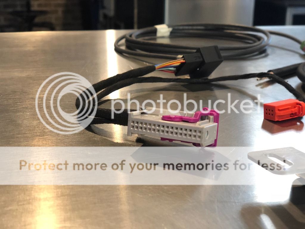
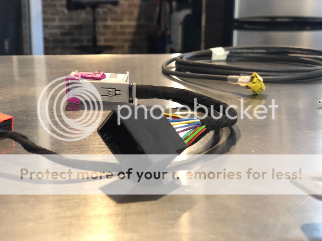
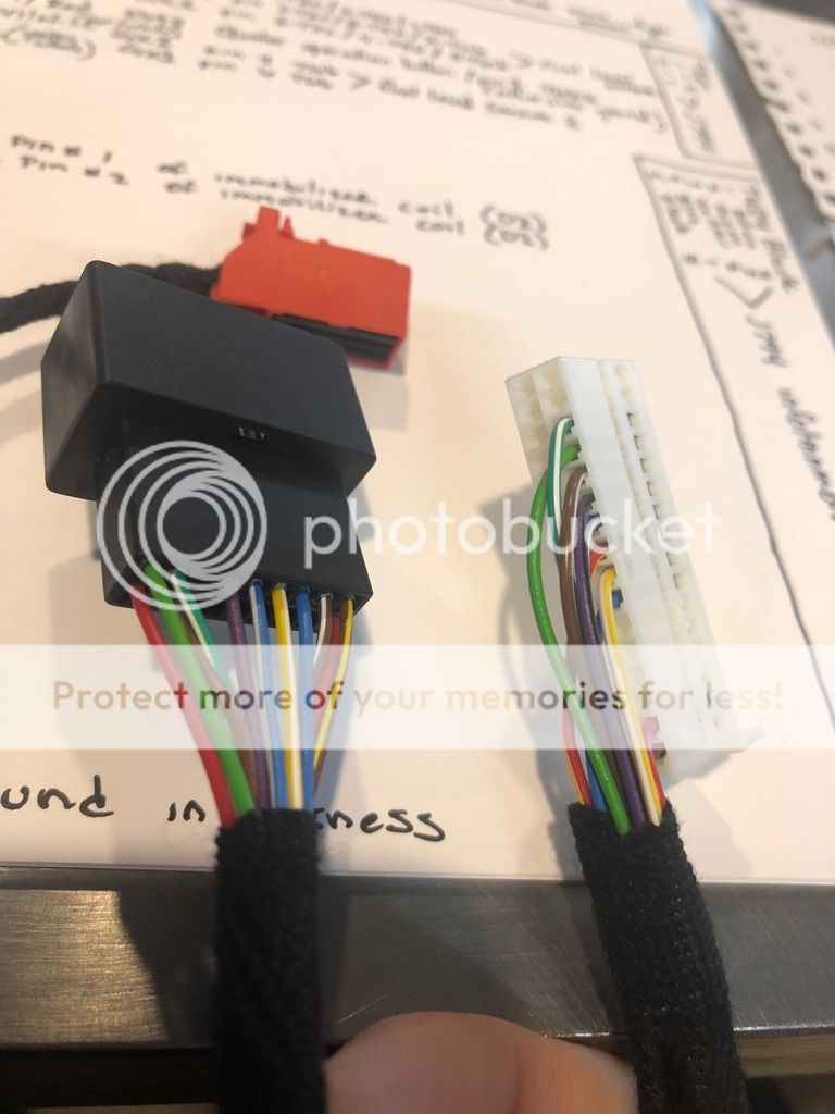
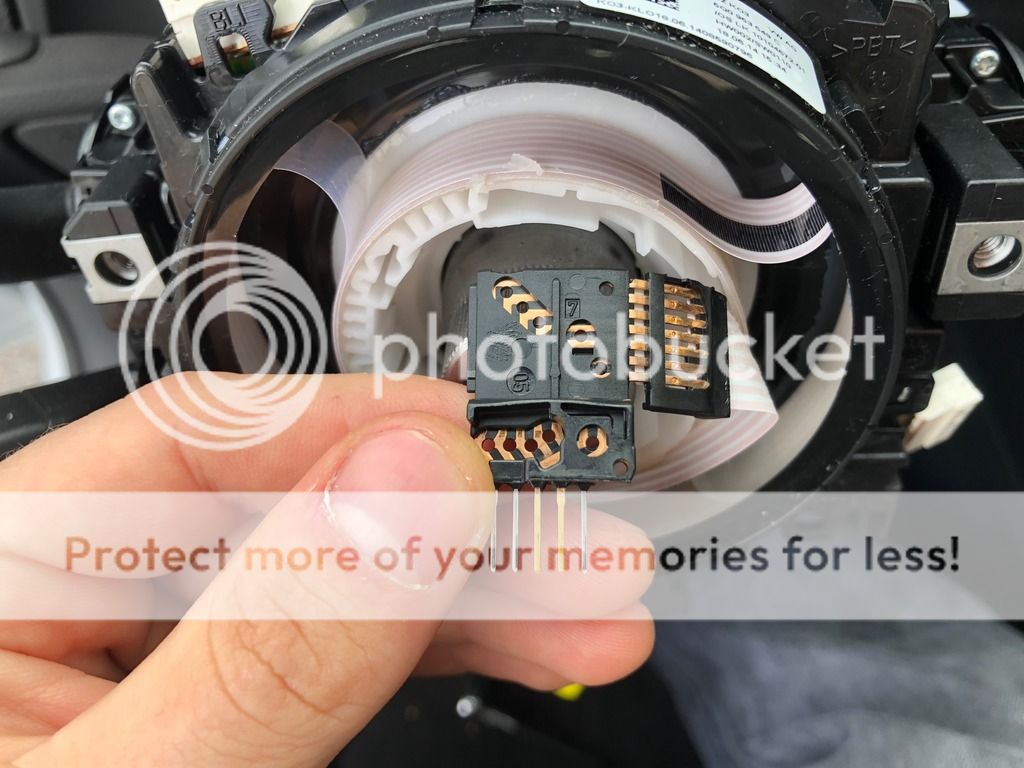
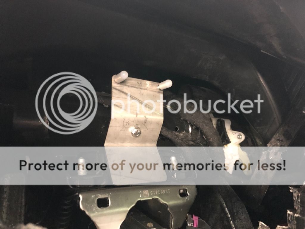
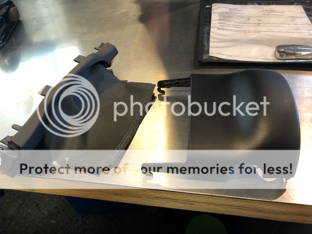
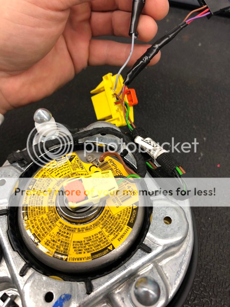
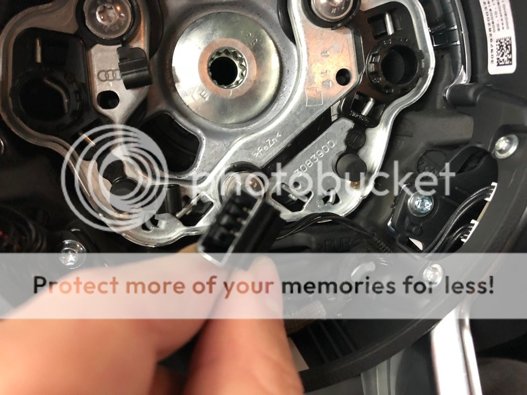
Here is the new harness once adjusted. Note, there is 1 gray Power wire going to the T4 connector at this time. I am unsure of the purpose of this wire at this time.
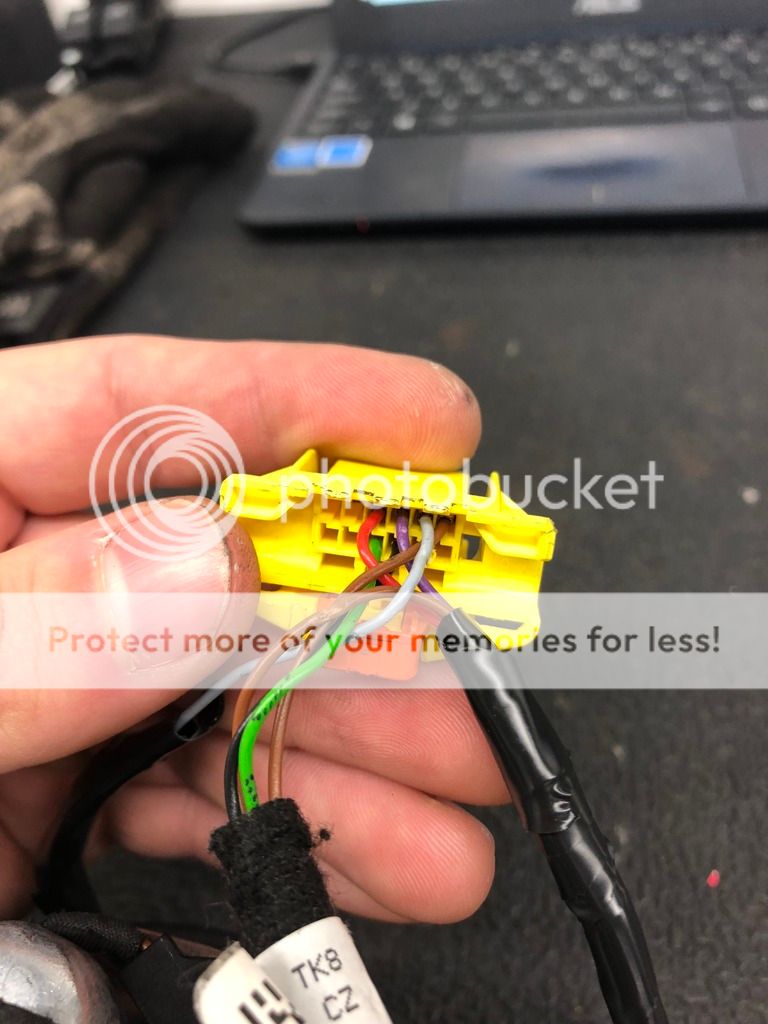
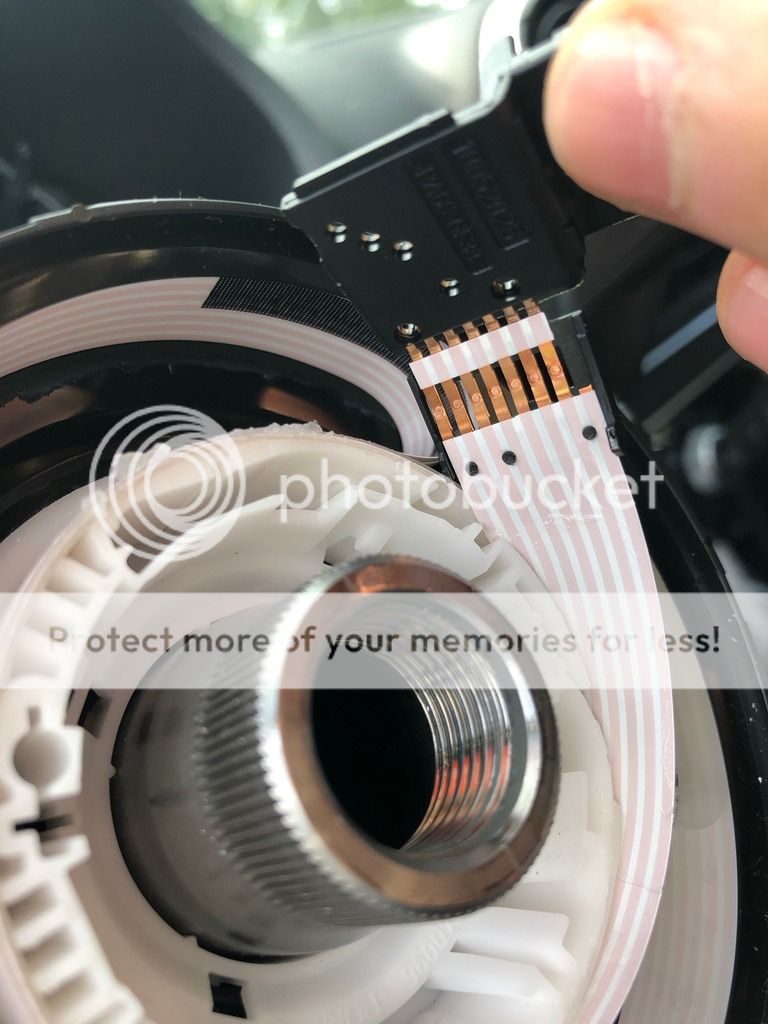
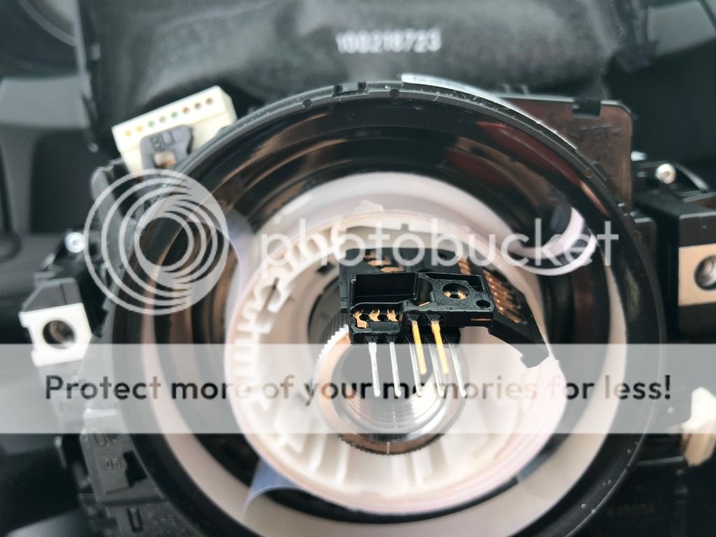
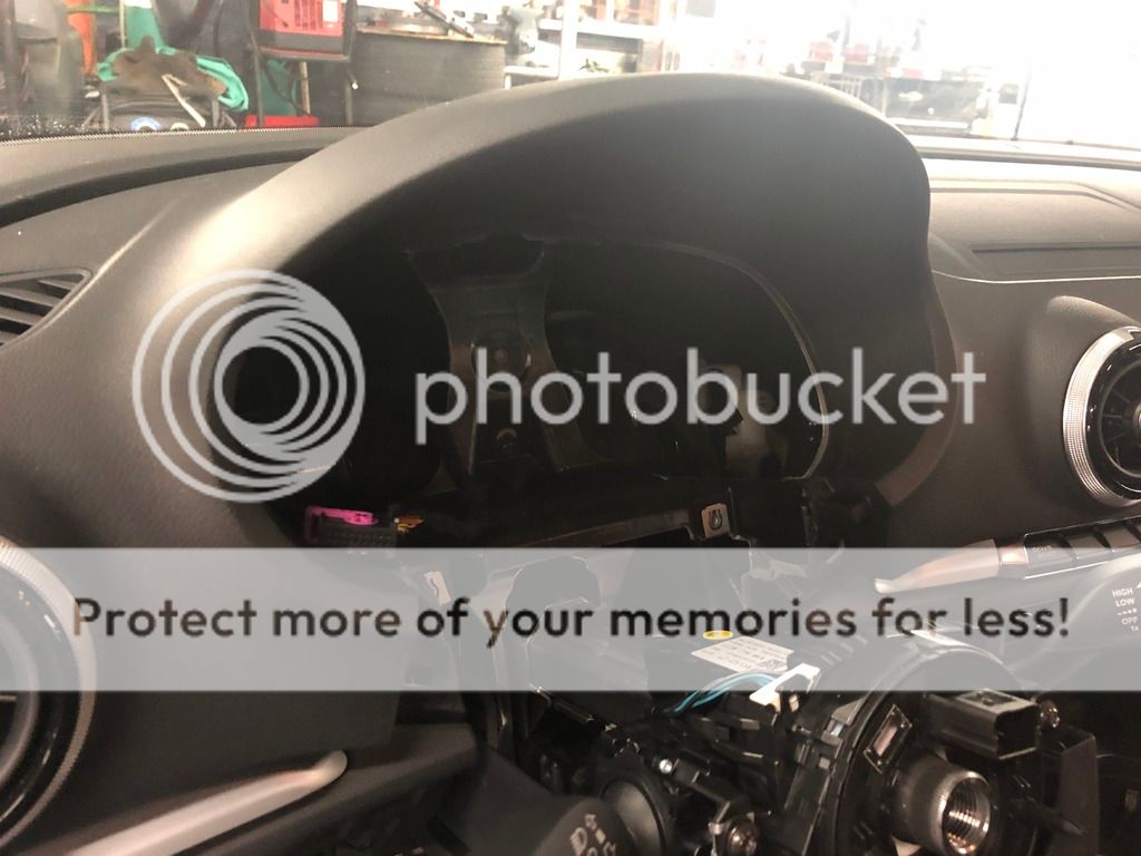
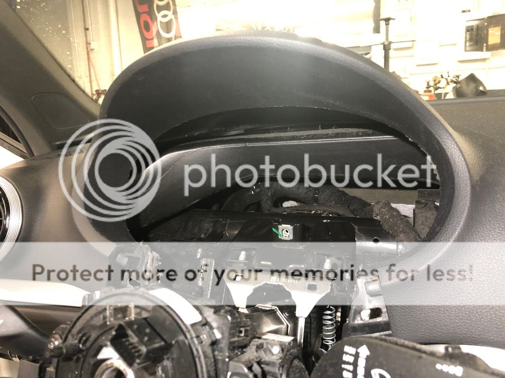
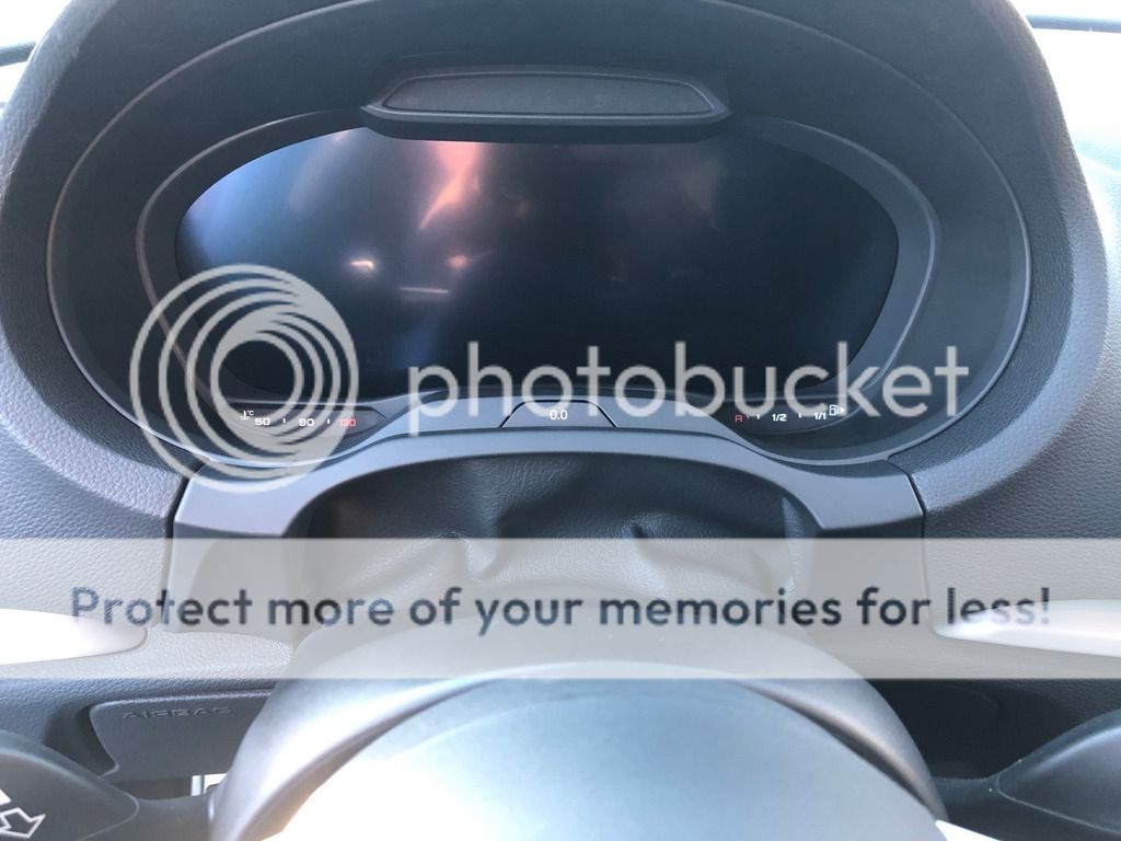
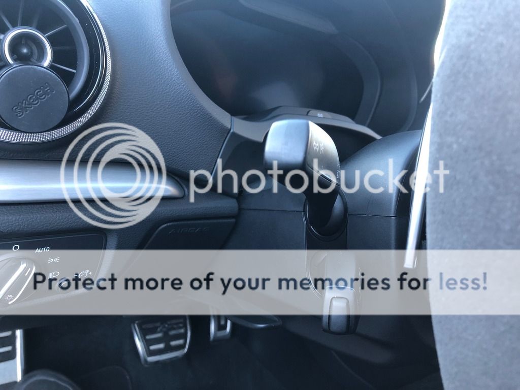
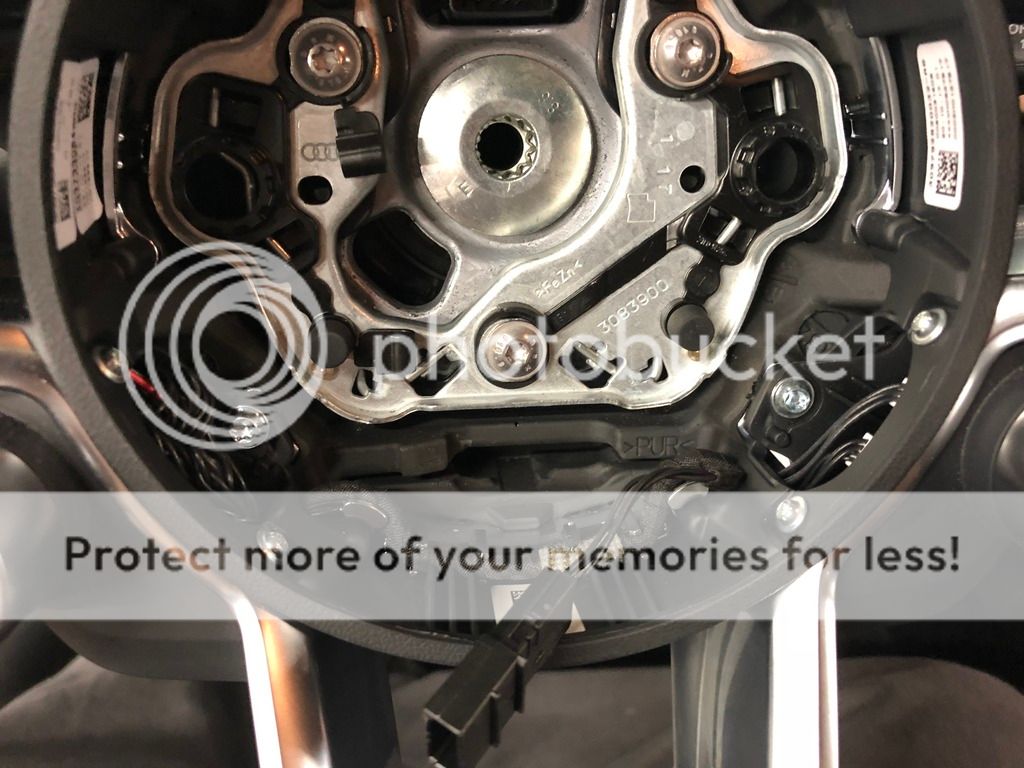
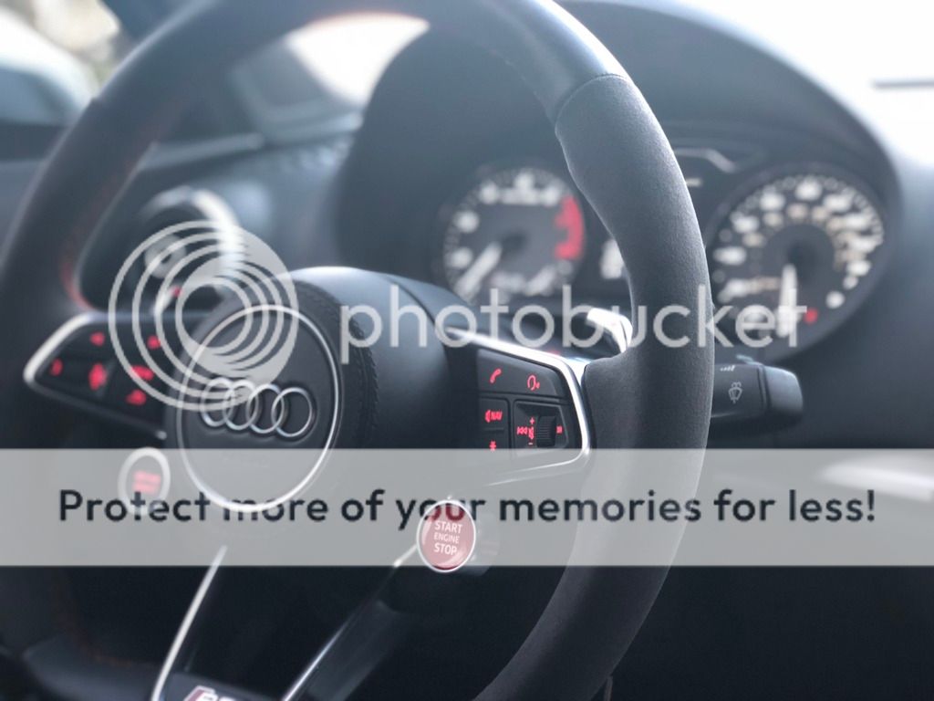
And here is a photo of the wheel installed with no airbag. You can see the clockspring with 2 pins on the top row, and 5 on the bottom, as well as the T6 connector above it.
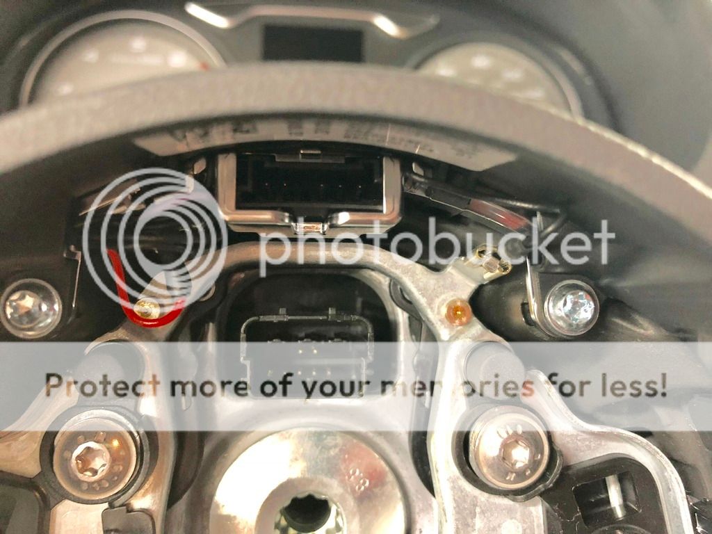
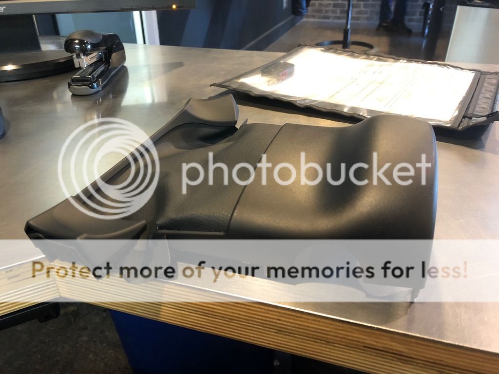
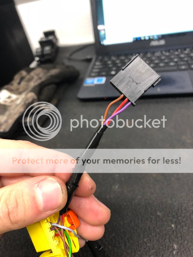
And here is the T4 connector that is simply for the Start / Stop and Drive Select Buttons.
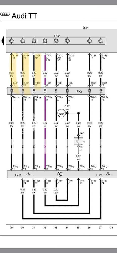
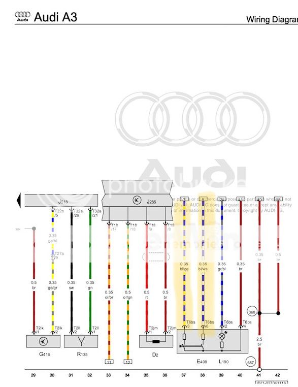
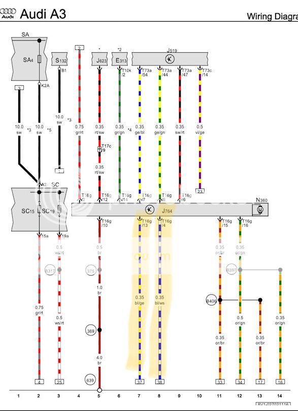
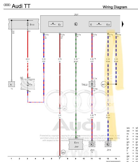
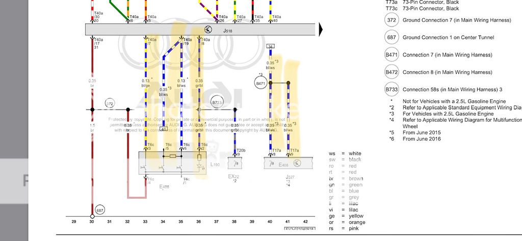
And for reference, here is the wiring diagram for the S3 followed by the diagram for the TTRS. If anyone would like to chime in and help solve this, that would be great. You can see all the black wires that are built within the TTRS wheel in the 3rd and 4th photo.
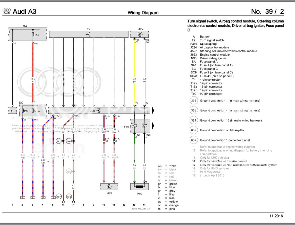
and the TTRS
There will be more updates as this progresses, and as parts arrive for the MIB and Virtual Cockpit! Any info, help, tips, etc, are greatly appreciated! I look forward to seeing this progress!
and here is an AutoScan just because.
The updated steering wheel is necessary to have access to the "VIEW" button, to change display settings on the VC.
I will pre-face this by saying that I haven't found another thread with a car in the US, that has been capable of retrofitting the VC, or even attempted. I know there are a few guys in EU that have done this, and now MK7 Active Display retrofits are popping up here in the US as well. I have seen a couple of people that have retrofitted the TTRS wheel into the MQB cars with only partial functions. I am hoping that we can have the wheel work 100%.
My first challenge was to find a MIB2 Unit that could have NAR maps installed, and them work correctly, and also have CarPlay. Sirius and DAB (Digital Radio) aren't really a huge concern of mine. I created a list of part numbers of MIB2 units from US MQB cars with Parts Link. Unfortunately with it only being around for a couple of years so far, the cheapest NAR MIB2 unit I could find was still $4k +. This simply is not an option due to the total cost that the project would come to. After speaking with multiple companies over sea, I ended up working with APG in Poland who specializes in retrofitting MIB/Clusters.
They say they are able to source me a MIB2 unit, with NAR maps installed, CarPlay enabled, Sirius, and DAB. For those not familiar, Audi and VW now uses SwaP codes to unlock these features on cars that wish to upgrade. After researching, even though my S3 came with NAV, it is not the Google Maps style of Nav on the new cars. My VIN also isn't eligible for the CarPlay FEC code due to it not being available during my production or MIB1. It seemed as though my only option was to get an unlocked unit.
And here we are, at the beginning of this long road. I will say again, I am not sure that the VC will work 100% but I want to get it as close as possible and have this serve as the guide to help people who wish to do this in the future.
Parts that have been ordered so far:
-TTRS Steering wheel with airbag and harness
-LCD Instrument Cluster: 8V0-920-790-A
-MIB 2 Unit: 8V1-035-035 (There are multiple part numbers for this, depending on features and it is region specific)
-LCD Trim: 8V0-857-115
-HSD and MOST cables to run from the back of the MIB2 to the LCD
-Adapter harness for Cluster (Original is 18 pin, new cluster is 32 pin)
-Bracket for mounting LCD
-USB port for CarPlay and wiring
While we wait for the VC parts to arrive, the steering wheel needs to be installed.
Plug and play does work with the new steering wheel. The airbag connectors are different, but can easily be swapped. Both airbags are however, 1 stage airbags.
Here is where I ask for the first bit of help. The S3/A3 has a clockspring F350, separate from the the Steering Column Control Module J527. The TTRS using a 1 piece design that houses the clockspring, wiper stalk, and cruise control stalk. Here is the wiring layout for the yellow 12 pin connector on the clockspring from both steering wheels.
S3:
Pin 1:
Pin 2:
Pin 3: Black wire, Ground for N95 Igniter
Pin 4: Green wire, Power for N95 Igniter
Pin 5:
Pin 6:
Pin 7: Brown wire, Ground Connection that also goes to the Horn, and pin 3 of T4 connector on steering wheel.
Pin 8: Blue wire, Power for horn function, constant B+
Pin 9: Purple wire, LIN Bus, goes to Pin 1 of T4 on steering wheel.
Pin 10: White wire, constant B+ for steering wheel, goes to Pin 2 of T4 on steering wheel.
Pin 11: (Has pin on Clockspring, but no wire from steering wheel)
Pin 12:
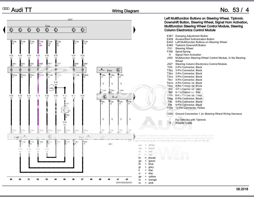
TTRS:
Pin 1: Gray wire, goes to Pin 2 of T4 connector for Start/Stop and Drive Select Buttons (Unknown Function)
Pin 2: Light gray wire, goes to Pin 1 of T4 connector for Start/Stop and Drive Select Buttons (Unknown Function)
Pin 3: Black wire, Ground for N95 Igniter
Pin 4: Green wire, Power for N95 Igniter
Pin 5:
Pin 6:
Pin 7:
Pin 8: Brown wire, Ground Connection that also goes to the Horn, and pin 3 of T6 connector on steering wheel.
Pin 9: Purple wire, LIN Bus, goes to Pin 1 of T6 on steering wheel.
Pin 10: Red wire, constant B+ for steering wheel, goes to Pin 2 of T6 on steering wheel.
Pin 11: Gray w/ Red Stripe wire, goes to Pin 3 of T4 connector for Start/Stop and Drive Select Buttons
Pin 12:
I was able to get basic functions working on the wheel. 80% of the buttons, the lights, and the horn.
Using the harness from the TTRS wheel:
Move the brown wire from Pin 8 to Pin 7. Its that simple.
This gives you Purple, Red, and Brown on the T6 Connector at the top of the wheel. This provides all the basic functions.
The wheel has a T4 connector with 3 wires for the Start/ Stop and Drive select Buttons. Only 3 wires. The S3 clockspring only has 2 remaining pins though.
Pin 8, and Pin 11. Both of which have B+ when the key is on, and again, I am left with 3 wires for those two buttons.
Are these wires Power, Ground, and LIN?
Signal, signal, and ground?
The wiring diagram is very vague and only has the wires listed as black. No colors are listed. Another fun fact, is the Start/Stop button currently also activates the horn :thumbs:
Here is the new harness once adjusted. Note, there is 1 gray Power wire going to the T4 connector at this time. I am unsure of the purpose of this wire at this time.
And here is a photo of the wheel installed with no airbag. You can see the clockspring with 2 pins on the top row, and 5 on the bottom, as well as the T6 connector above it.
And here is the T4 connector that is simply for the Start / Stop and Drive Select Buttons.
And for reference, here is the wiring diagram for the S3 followed by the diagram for the TTRS. If anyone would like to chime in and help solve this, that would be great. You can see all the black wires that are built within the TTRS wheel in the 3rd and 4th photo.
and the TTRS
There will be more updates as this progresses, and as parts arrive for the MIB and Virtual Cockpit! Any info, help, tips, etc, are greatly appreciated! I look forward to seeing this progress!
and here is an AutoScan just because.
Code:
Thursday,11,October,2018,13:33:26:16731
VCDS -- Windows Based VAG/VAS Emulator Running on Windows 10 x86
VCDS Version: 18.9.0.2  HEX-NET CB: 0.4436.4
Data version: 20180927 DS296.0
www.Ross-Tech.com


VIN: WAUBFGFF8F1xxxxxx   License Plate:
Mileage: 69245km-43026mi   Repair Order:


--------------------------------------------------------------------------------
--------------------------------------------------------------------------------


Chassis Type: FF-AU37 (5Q0)
Scan: 01 02 03 05 08 09 15 16 17 19 22 2B 42 44 52 55 5F A9 BB BC


VIN: WAUBFGFF8F1xxxxxx   Mileage: 69245km-43026miles

01-Engine -- Status: OK 0000
02-Auto Trans -- Status: OK 0000
03-ABS Brakes -- Status: OK 0000
05-Acc/Start Auth. -- Status: OK 0000
08-Auto HVAC -- Status: OK 0000
09-Cent. Elect. -- Status: Malfunction 0010
15-Airbags -- Status: OK 0000
16-Steering wheel -- Status: Malfunction 0010
17-Instruments -- Status: OK 0000
19-CAN Gateway -- Status: OK 0000
22-AWD -- Status: OK 0000
2B-Steer. Col. Lock -- Status: OK 0000
42-Door Elect, Driver -- Status: OK 0000
44-Steering Assist -- Status: OK 0000
52-Door Elect, Pass. -- Status: OK 0000
55-Headlight Range -- Status: OK 0000
5F-Information Electr. -- Status: Malfunction 0010
A9-Struct. Borne Sound -- Status: OK 0000
BB-Door Rear Drv -- Status: OK 0000
BC-Door Rear Pass -- Status: OK 0000
-------------------------------------------------------------------------------
Address 01: Engine
Cannot be reached

-------------------------------------------------------------------------------
Address 02: Auto Trans (J743)       Labels: 0D9-927-770.clb
   Part No SW: 0D9 300 012 L    HW: 02E 927 770 AQ
   Component: DQ250-6A MQB  H52 4521
   Revision: 05852204    Serial number: TFK01405260976
   Coding: 0014
   Shop #: WSC 04742 780 00200
   ASAM Dataset: EV_TCMDQ250021 001001
   ROD: EV_TCMDQ250021.rod
   VCID: 1F0E0B4706FC87B2CC-804A

No fault code found.

-------------------------------------------------------------------------------
Address 03: ABS Brakes (J104)       Labels: 5Q0-907-379-IPB-V1.clb
   Part No SW: 5Q0 907 379 L    HW: 5Q0 907 379 G
   Component: ESC           H31 0471
   Revision: 00000000    Serial number: 61574000002972
   Coding: 31FF6B9254230A70017F030341C4698CD62A5080C08296B6024100588608
   Shop #: WSC 06385 790 00016
   ASAM Dataset: EV_Brake1UDSContiMK100IPB 033001
   ROD: EV_Brake1UDSContiMK100IPB_033_AU37.rod
   VCID: 45C2B92FC4E0BD62A6-8010

No fault code found.

-------------------------------------------------------------------------------
Address 05: Acc/Start Auth. (J518)       Labels:| 5Q0-959-435.clb
   Part No SW: 5Q0 959 435 A    HW: 5Q0 959 435
   Component: VWKESSYMQB    021 0604
   Revision: 00021000    Serial number: 0337502114
   Coding: 030C0C
   Shop #: WSC 00000 000 00000
   ASAM Dataset: EV_KessyHellaMQBAB 002011
   ROD: EV_KessyHellaMQBAB_002.rod
   VCID: 3A38DAD3BD1EC29ADB-806E

No fault code found.

-------------------------------------------------------------------------------
Address 08: Auto HVAC (E87)       Labels:| 8V0-820-043.clb
   Part No SW: 8V0 820 043 D    HW: 8V0 820 043 D
   Component: AC Automat    H13 0052
   Revision: 20026000    Serial number: 00000000352798
   Coding: 03000014010000000000000000001400
   Shop #: WSC 06385 790 00016
   ASAM Dataset: EV_AirCondiFrontVaAU37X 008020
   ROD: EV_AirCondiFrontVaAU37X.rod
   VCID: 3326F7F79A7433D218-8066

   Relative humidity sensor in fresh air intake duct:
   Subsystem 1 - Part No SW: 4H0 907 658     HW: 4H0 907 658
   Component: AQ_Hum_Sensor  H03 0003
   Serial number: 8E28C137000000000001

No fault code found.

-------------------------------------------------------------------------------
Address 09: Cent. Elect. (J519)       Labels:| 5Q0-937-08X-HV1.clb
   Part No SW: 5Q0 937 085 AC    HW: 5Q0 937 085 AC
   Component: BCM MQBAB HNA H18 0134
   Serial number: 01011415600179
   Coding: 04151A46C04122F541C04004511807A00800000000000000000000000000
   Shop #: WSC 06385 790 00016
   ASAM Dataset: EV_BCMCONTI 013000
   ROD: EV_BCMBOSCH_013.rod
   VCID: 7AB81AD3FD9E029A9B-802E

   Control Unit For Wiper Motor:
   Subsystem 1 - Part No SW: 8V1 955 119 C    HW: 8V1 955 119 A  Labels: 5QX-955-119-V1.CLB
   Component: WWS371 140607  042 0585
   Serial number:         140616050335
   Coding: 0A47F7

   Rain Light Recognition Sensor:
   Subsystem 2 - Part No SW: 8U0 955 559 B    HW: 8U0 955 559 B  Labels: 8U0-955-559.CLB
   Component: G397_RLFS  H06 0002
   Serial number: 22746941
   Coding: 00006C

   Light switch:
   Subsystem 3 - Part No SW: 8V0 941 531 K    HW: 8V0 941 531 K
   Component: E1 - LDS MQB  H05 0032
   Serial number: 13 04 2014  00001159

   Alarm horn:
   Subsystem 4 - Part No SW: 5Q0 951 605     HW: 5Q0 951 605
   Component: Sirene, DWA  004 0311
   Serial number: 00000000000030053299

   Sun Roof:
   Subsystem 5 - Part No SW: 8V3 959 591     HW: 8V3 959 591
   Component: J245 PS73.014  H02 0007
   Serial number:     WOO30038644
   Coding: 101F00

2 Faults Found:
197644 - Control Circuit for Fuel Tank Flap
          B1263 01 [009] - Electrical Failure
          Confirmed - Tested Since Memory Clear
             Freeze Frame:
                    Fault Status: 00000001
                    Fault Priority: 4
                    Fault Frequency: 1
                    Reset counter: 195
                    Date: 2000.00.00
                    Time: 00:00:00

204290 - Remote key 1
          B1479 18 [009] - Current Too Low
          Confirmed - Tested Since Memory Clear
             Freeze Frame:
                    Fault Status: 00000001
                    Fault Priority: 4
                    Fault Frequency: 1
                    Reset counter: 195
                    Mileage: 69245 km
                    Date: 2018.10.11
                    Time: 13:27:30


-------------------------------------------------------------------------------
Address 15: Airbags (J234)       Labels:| 5Q0-959-655.clb
   Part No SW: 5Q0 959 655 J    HW: 5Q0 959 655 J
   Component: AirbagVW20    009 0825
   Serial number: 003GCR00FAC9
   Coding: 9DCCFCC0000000005000001AC24800000065
   Shop #: WSC 06385 790 00016
   ASAM Dataset: EV_AirbaVW20SMEVW37X 002138
   ROD: EV_AirbaVW20SMEVW37X.rod
   VCID: 47DEB327FEECAF7254-8012

   Belt Pretensioner left:
   Subsystem 1 - Part No SW: 5G0 980 945 B    HW: 5G0 980 945 B
   Component: BeltPretRevFL  H35 0341
   Serial number: 34178311A16061440949
   Coding: 333135

   Belt Pretensioner right:
   Subsystem 2 - Part No SW: 5G0 980 946 B    HW: 5G0 980 946 B
   Component: BeltPretRevFR  H35 0341
   Serial number: 34178312A16061440726
   Coding: 333135

   Occupant Detection:
   Subsystem 3 - Part No SW: 5C6 959 339 B    HW: 5C6 959 339 B
   Component: BF-Gewichtss.  H10 0046
   Serial number: 6940000Y1400015LZP0G
   Coding: 303230

   Side Sensor Driver Front:
   Subsystem 4 - Part No SW: -----------    HW: 480 001 106 14
   Component: SideSensor_Df  001 0887
   Serial number: 35700000000EB8309F0W
   Coding: 2D2D2D

   Side Sensor Passenger Front:
   Subsystem 5 - Part No SW: -----------    HW: 480 001 106 14
   Component: SideSensor_Pf  001 0887
   Serial number: 358000000006B8309F0P
   Coding: 2D2D2D

   Side Sensor Driver Rear:
   Subsystem 6 - Part No SW: -----------    HW: 480 400 406 14
   Component: SideSensor_Dr  001 6149
   Serial number: 3510002B5156EA05B171
   Coding: 2D2D2D

   Side Sensor Passenger Rear:
   Subsystem 7 - Part No SW: -----------    HW: 480 400 406 14
   Component: SideSensor_Pr  001 6149
   Serial number: 3520002C3156EA01B1C2
   Coding: 2D2D2D

   Front Sensor Driver:
   Subsystem 8 - Part No SW: -----------    HW: 480 401 004 14
   Component: FrontSensor_D  001 6149
   Serial number: 3550002C31529DF1C248
   Coding: 2D2D2D

   Front Sensor Passenger:
   Subsystem 9 - Part No SW: -----------    HW: 480 401 004 14
   Component: FrontSensor_P  001 6149
   Serial number: 3560002C31529DF2E24C
   Coding: 2D2D2D

No fault code found.

-------------------------------------------------------------------------------
Address 16: Steering wheel (J527)       Labels:| 5Q0-953-549.clb
   Part No SW: 8V0 953 521 CP    HW: 5Q0 953 549 C
   Component: Lenks. Modul  002 0110
   Revision: --------    Serial number: 18061408490796
   Coding: A218
   Shop #: WSC 06385 790 00016
   ASAM Dataset: EV_SMLSKLOMQB 017001
   ROD: EV_SMLSKLOMQB_012_AU37.rod
   VCID: 0A584A13AD7E121A8B-805E

1 Fault Found:
227387 - Windshield Wiper/Washer Switch
          B1149 13 [009] - Open Circuit
          Confirmed - Tested Since Memory Clear
             Freeze Frame:
                    Fault Status: 00000001
                    Fault Priority: 3
                    Fault Frequency: 1
                    Reset counter: 194
                    Mileage: 69245 km
                    Date: 2018.10.11
                    Time: 13:02:24

                    Operating time: 87989 min
                    Supply voltage: Terminal 30: 12.4 V
                    Vehicle speed: 0 km/h
                    Voltage at switch: 4.98 V
                    Terminal 15 status: active
                    System status: 30
                    FF U Wischer AD value: 230
                    FF U Wish Wash AD value: 229
                    FF U Intervall Poti AD value: 61
                    FF U MFA AD value: 252


-------------------------------------------------------------------------------
Address 17: Instruments (J285)       Labels:| 5G0-920-XXX-17.clb-SRI3
   Part No SW: 8V0 920 970 S    HW: 8V0 920 970 S
   Component: KOMBI         H02 4291
   Coding: 0BED181B2B80D7050201E8001800000000000000
   Shop #: WSC 06385 790 00016
   ASAM Dataset: EV_DashBoardVDDMQBAB 009040
   ROD: EV_DashBoardVDDMQBAB_009_VW37.rod
   VCID: 4CD48C0BE78A4C2A79-8018

No fault code found.

-------------------------------------------------------------------------------
Address 19: CAN Gateway (J533)       Labels:| 5Q0-907-530-V1.clb
   Part No SW: 5Q0 907 530 T    HW: 5Q0 907 530 M
   Component: GW MQB High   212 2186
   Revision: --------    Serial number: 11061410800771
   Coding: 0101000820085A005B00022C180B00000001010000000000000000000000
   Shop #: WSC 06385 790 00016
   ASAM Dataset: EV_GatewConti 011017
   ROD: EV_GatewConti_011_VW37.rod
   VCID: 42C8A233D5CE8A5A83-8016

   Alternator:

   Multi Function Steering Wheel Control Module:
   Subsystem 2 - Part No SW: 8S0 951 523 K    HW: 8S0 951 523 K
   Component: J453 MFL  H01 0002
   Serial number: 20170220132047 RD128

No fault code found.

-------------------------------------------------------------------------------
Address 22: AWD (J492)       Labels:* 0CQ-907-554.clb
   Part No SW: 0CQ 907 554 D    HW: 0CQ 907 554 D
   Component: Haldex4Motion H52 7076
   Serial number: HA1-00013.05.14
   Coding: 0001
   Shop #: WSC 06385 790 00016
   ASAM Dataset: EV_AllWheelContrHA1VW37X 002001
   ROD: EV_AllWheelContrHA1VW37X.rod
   VCID: 46C0BE23F9E6B67AAF-8012

No fault code found.

-------------------------------------------------------------------------------
Address 2B: Steer. Col. Lock (J764)       Labels:* 5Q0-905-861.clb
   Part No SW: 5Q0 905 861 A    HW: 5Q0 905 861 A
   Component: ELV-MQBA      H01 0120
   Revision: 00000000    Serial number: 14000152811004
   Coding: 5D00000000000000
   Shop #: WSC 06385 790 00016
   ASAM Dataset: EV_ELVMarquMQB 004111
   ROD: EV_ELVMarquMQB.rod
   VCID: 3424F4EB9F7A34EA01-8060

No fault code found.

-------------------------------------------------------------------------------
Address 42: Door Elect, Driver (J386)       Labels:| 5QX-959-X93-42.clb
   Part No SW: 5Q0 959 393 B    HW: 5Q0 959 393 B
   Component: TSG FS        020 0025
   Serial number: 30051402090339
   Coding: 00101F204000048000000002
   Shop #: WSC 06385 790 00016
   ASAM Dataset: EV_DCUDriveSideEWMINKLO 006003
   ROD: EV_DCUDriveSideEWMAXCONT.rod
   VCID: 3E30D6C3A136EEBAE7-806A

No fault code found.

-------------------------------------------------------------------------------
Address 44: Steering Assist (J500)       Labels:| 5Q0-909-144.clb
   Part No SW: 3Q0 909 144 F    HW: 3Q0 909 144 F
   Component: EPS_MQB_ZFLS  503 5043
   Coding: 8102
   Shop #: WSC 06385 790 00016
   ASAM Dataset: EV_SteerAssisMQB 010031
   ROD: EV_SteerAssisMQB_010.rod
   VCID: 3522C9EF94002DE236-8060

No fault code found.

-------------------------------------------------------------------------------
Address 52: Door Elect, Pass. (J387)       Labels:| 5QX-959-X92-52.clb
   Part No SW: 5Q0 959 392 B    HW: 5Q0 959 392 B
   Component: TSG BFS       020 0025
   Serial number: 01061401101471
   Coding: 001017204000048000000002
   Shop #: WSC 06385 790 00016
   ASAM Dataset: EV_DCUPasseSideEWMINKLO 006003
   ROD: EV_DCUPasseSideEWMAXCONT.rod
   VCID: 3D32D1CFAC30F5A2FE-8068

No fault code found.

-------------------------------------------------------------------------------
Address 55: Headlight Range (J431)       Labels:| 5Q0-907-357.clb
   Part No SW: 5Q0 907 357     HW: 6R0 907 357 A
   Component: LWR-ECU       005 0080
   Revision: --------    Serial number: --------------
   Coding: 012A000101000000
   Shop #: WSC 06385 790 00016
   ASAM Dataset: EV_HeadlRegulVWLWRMQB 001110
   ROD: EV_HeadlRegulVWLWRMQB.rod
   VCID: 75A209EFD4806DE2F6-8020

No fault code found.

-------------------------------------------------------------------------------
Address 5F: Information Electr. (J794)       Labels:* None
   Part No SW: 8V0 035 039 C    HW: 8V0 035 039 B
   Component: MU-H-LNS-US   H44 0403
   Serial number: A539A0J7505175
   Coding: 01730102FF0A000021220001041A00102F000205010001047E
   Shop #: WSC 29707 001 1048576
   ASAM Dataset: EV_MUHig6C3HBAS 001040
   ROD: EV_MUHig6C3HBAS_AU37.rod
   VCID: 3522C9EF94002DE236-8060

   Data medium:
   Subsystem 1 - Part No SW: V03 959 800 T    HW: -----------
   Component: NAR 2016  --- 0048
   Serial number: --------------------

   Display unit 1 for multimedia system:
   Subsystem 2 - Part No SW: 8V0 919 604 C    HW: 8V0 919 604 C
   Component: DU High  H49 0013
   Serial number: AUZ8Z9EY201511

   Multimedia Operating Unit:
   Subsystem 3 - Part No SW: 8V0 919 614 S    HW: 8V0 919 614 E
   Component: ControlUnit_H  H64 0766
   Serial number: C1000022051400020165

   Compact Disc Database:
   Subsystem 4 - Part No SW: V03 959 800 EG    HW: -----------
   Component: Gracenote  --- 3006
   Serial number: --------------------

3 Faults Found:
0020 - Tuner for Satelite Radio
          B11CF 53 [009] - Deactivated
          Confirmed - Tested Since Memory Clear
             Freeze Frame:
                    Fault Status: 00000001
                    Fault Priority: 4
                    Fault Frequency: 1
                    Reset counter: 124
                    Mileage: 54940 km
                    Date: 2018.02.22
                    Time: 13:58:48

                    Voltage terminal 30: 12.6 V
                    Satellite radio tuner status-Satellite radio antenna status: Electrical OK
                    Satellite radio tuner status-Channel selection for satellite radio: 0
                    Satellite radio tuner status-Audio Signal: Not available
                    Satellite radio tuner status-Antenna current: 0 mA
                    Satellite radio tuner status-Reception quality: No_signal
                    Satellite radio tuner status-SDARS Flash Regional code: US_Audio_Traffic_Travellink

3084 - GSM antenna 2
          B1533 13 [009] - Open Circuit
          Confirmed - Tested Since Memory Clear
             Freeze Frame:
                    Fault Status: 00000001
                    Fault Priority: 4
                    Fault Frequency: 19
                    Reset counter: 129
                    Mileage: 54940 km
                    Date: 2018.02.22
                    Time: 13:58:49

                    Voltage terminal 30: 12.5 V

6708 - Databus
          U1121 00 [008] - Missing Message
          [Engine: no communication]
          Intermittent - Confirmed - Tested Since Memory Clear
             Freeze Frame:
                    Fault Status: 00000001
                    Fault Priority: 6
                    Fault Frequency: 3
                    Reset counter: 235
                    Mileage: 67082 km
                    Date: 2018.08.31
                    Time: 17:50:52

                    Voltage terminal 30: 14.6 V
                    Network diagnosis-Status: Enabled


-------------------------------------------------------------------------------
Address A9: Struct. Borne Sound (J869)       Labels: 4H0-907-159.clb
   Part No SW: 8V0 907 159     HW: 4H0 907 159 A
   Component: SAS-GEN 2     H06 0012
   Serial number: 140521201825
   ASAM Dataset: EV_SoundActuaGen2AU64X 003010
   ROD: EV_SoundActuaGen2AU64X.rod
   VCID: 7DB211CFECB035A2BE-8028

No fault code found.

-------------------------------------------------------------------------------
Address BB: Door Rear Drv (J388)       Labels:* None
   Part No SW: 5Q0 959 395 B    HW: 5Q0 959 395 B
   Component: TSG HFS       020 0025
   Serial number: 10061404081400
   Coding: 000017204000048000000002
   Shop #: WSC 06385 790 00016
   ASAM Dataset: EV_DCURearDriveMINKLO 006003
   ROD: EV_DCURearDriveMAXCONT.rod
   VCID: 40CCA83BDBC2984A95-8014

No fault code found.

-------------------------------------------------------------------------------
Address BC: Door Rear Pass (J389)       Labels:* None
   Part No SW: 5Q0 959 395 B    HW: 5Q0 959 395 B
   Component: TSG HBFS      020 0025
   Serial number: 10061403111400
   Coding: 000017204000048000000002
   Shop #: WSC 06385 790 00016
   ASAM Dataset: EV_DCURearPasseMINKLO 006003
   ROD: EV_DCURearPasseMAXCONT.rod
   VCID: 40CCA83BDBC2984A95-8014

No fault code found.

End----------(Elapsed Time: 01:57, VBatt start/end: 12.6V/12.6V)-----------

--------------------------------------------------------------------------------
--------------------------------------------------------------------------------


Address 16: DTCs cleared