Waaaaaay over-due an update. I just haven't had the time lately to get on the car, and have other distractions, but fear not, I'm back and I'm ready for action!
Over the Christmas holidays I started to change the configuration of my ECU. I'm upgrading it from a MS3 to an 'MS3X', which taps the full potential of the processor. Allowing fully sequential fuel and spark on up to 8 cylinder engines. it also gives me;
- 6 programmable medium current outputs (can be used for boost control, pwm idle control, relay outputs... whatever i want.
- 4 switch inputs, switch tables, start data logging, launch control...
- Cam sensor input (required for sequential fuel)
- 3 extra analogue inputs (could be used for additional sensors, anything that outputs a voltage to the ECU)
I have also decided to add the internal knock sensing module to my ECU, which provides sophisticated programmable knock detection (you can select different ****** conditions, and whether it detects per cylinder or not) I'll be a lot happier tuning the engine knowing the ECU is watching to make sure i don't get too silly with the timing table...
So the first thing to do, was take the ECU back out the car, and remove all the modifications I made, when I built it. The reason being, at the time of assembly, I planned to keep it simple and run batch fire injection and wasted spark ignition. Plans have changed, I'm still going to be using a Ford EDIS coil in wasted spark for now, but the 'igniter' MOSFETs will now be located near the coil, instead of inside the ECU itself, which has a few advantages IE shorter high current paths, and reduced electrical noise inside the ECU. The injector drivers were also removed, as these are now handled by the expansion board.
The MS3 main board with mods removed, and components returned to their original positions;

Added the Knock module to the MS3 CPU board (SPR3 + SPR4 are now my knock sensor input pins)
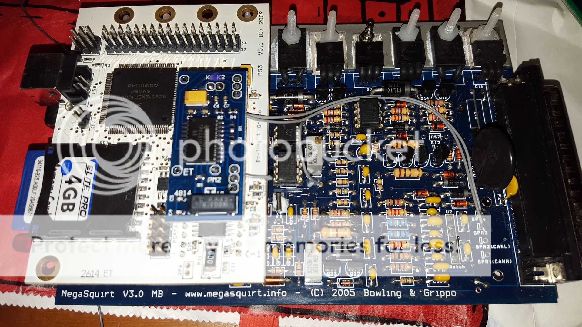
Trial fitted the MS3X board;


Was pretty happy with that, so called it a night, and the next morning I started pulling apart the wiring harness I made previously, and began figuring out where all the spaghetti needs to go.
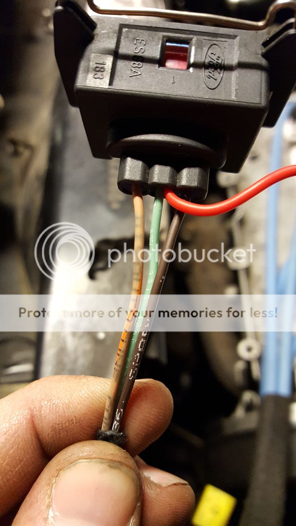
Knock sensor wires salvaged from the OEM loom;

I have two non-interchangeable plugs, so they cannot be plugged in the wrong way round. one Is used primarily for sensor inputs and outputs from the MS3 main board, the other is used for injector outputs, and other functions from the MS3X.
On the left is the injector wiring that i have just moved over to it's new home on the 'MS3X' plug. The Violet wires are +12v supply, the green and blue wires are the individual injectors that ground through the ECU FETs, turning them 'on'.

Then there's the other side of the loom, that goes from the bulkhead plug to the ECU. This time I didn't buy a pre-made harness, so I got busy with the soldering iron;


The wires grouped in the sleeving are the 4 grey wires for switch inputs (steering wheel) the other 4 are logic level spark ouptuts. Like i mentioned earlier, I'm sticking with wasted spark for now, so only really need 2 spark outputs, but I chose to run the other 2 wires in case I later decide to go with a COP arrangement, or some other type of fully sequential spark.
Buttoned it all up and it looked like this:

Punched a fresh hole in the ECU plate and fitted a grommet;


You might recall I said I fitted the knock module, and SPR3+4 were the inputs, well... SPR4 used to be used for SPARK B output. Which means I had to un-pick the ignition wires that went to the FORD EDIS coil in the bulkhead to remove the wire.
With the wire removed and fitted into it's new home in the MS3X bulkhead plug, I decided that was a good point to call it a day, and took some more pictures of the car, just to remind myself what it looks like...


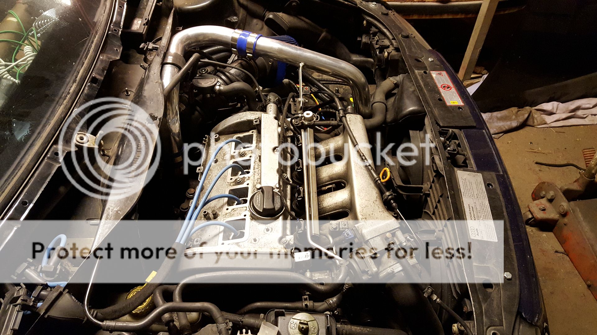
Thanks for reading
")


 Just let me know mate


