Charlie Farley's 2.0tfsi Full PCV Delete project, and why you need to do it too.

The info was from this site but they are standard hydraulic fittings so readily available from most good sources , prices vary a bit depending on the choice of material , stainless or brass or other so shop around for the best price.

https://www.thehosemaster.co.uk/
 
  • Like
Reactions: Dani_B19
have a good look through there fittings chap, there are numerous possible ways to do it but most need two fittings, the male x male adapter for the tank
and then the female hose barb.
here is another one but in stainless.
3/8" for the tank with 1" for the female hose barb.

1" (1) BSPT x 3/8" (2) BSPT Reducing Hex Nipple - 316 Stainless Steel
ssrc_2_3.jpg
 
Well I've just decided i'm going to modify my perfectly working setup to a more user friendly disassembly system.
having thought about it now , replacing the male hose barbs that screw directly into the tank to a two piece arrangement is the way to go for the following reasons.
1) hose removal for either cleaning or other reason becomes a much more user friendly and quicker process and does not involve struggling with stuck on hoses and clips etc, just loosen a nut to break the connection.

2) The catch tank will need removing on an annual basis to clean the main gauze mesh etc of gunk that has built up inside ,the tank will need to be fully removed and with the mishimoto tanks and other similar tanks where the residue container can be removed for cleaning and gaining access to the gauze mesh to clean , having a quick release type of setup for the hose removal makes for a much better way of gaining access to the tank and for removing the tank fully without messing around with hoses etc, just loosen the nuts and pull the hoses clear, how easy it that.....

I think this may become a setup modification permantly and I will update the main thread with the best and most appropriate parts I use.
 
Generic Stainless Steel 316 Barb Fitting Connector 3/4" Hose ID x 3/8" Male NPT Fuel Gas Water( Pack of 5 ) Amazon product

I bought mine here the closest to 25mm then i used plastic that can shrink with heatgun
 
So drom looking around i believe the following should be correct and also are the best prices i can find.
Screenshot 20180625 212539 Chrome
Screenshot 20180625 212424 Chrome


Anyone able to confirm?

Thanks.
 
looks right chap from a quick look, i'll double check just for you...
 
  • Like
Reactions: Dani_B19
Great post and well written up. Would be great to hear the price of a kit once you have it all honed in. I am very interested. The user friendly tweak is a brilliantly satisfying one
 
Evening all, hi again Rob, just sat and read this thread while watching the lightning outside lol, very interesting thread mate, and I'm defo gonna have to do this, if it will give the engine longevity. Did you get around to putting a complete kit together for sale Rob, as I'll be very interested in purchasing it, and it would save me a whole lot of tears as you can guarantee I'd get something wrong :blink: cheers marty.
 
Evening Chaps,
Bit of an update really on the kit front.
Kits are on hold for a while due to being let down by an engineering firm that have now decided they wont do small batch runs of the delete plate, min is 10 units I can order, why they have decided this now is beyond me frankly, but its a pain.
So if I can get 10 confirmed orders i'll make up the kits , i'll update the prices shortly aswell as they have changed a bit based on the manufacturing bods.

I am allways willing to help anyone out and that includes these kits but I cant be out of pocket with them , i'm not making any profit just covering my costs really, more of a favour to audi-sport members as i'm not doing these anywhere else.

just a heads up for you all really.

have a good one chaps.

rob
 
  • Like
Reactions: boffin486 and Dani_B19
OK Rob that's great, I'd rather wait than get something wrong, put me down for one please when you get sorted mate as I think it will be well worth the wait. Cheers marty.
 
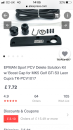
Considering the Epman block off plate is £20 on ebay or £12 on Ali express is it not cheaper/feasible to drill and tap these for catch can fittings?
 
not sure what part you are describing chap, as there are no plates on ebay at present , maybe you can clarify

rgds
rob
 

Attachments

  • D2528FB2-2450-49B4-B684-12B4E87BA1B2.png
    D2528FB2-2450-49B4-B684-12B4E87BA1B2.png
    294.6 KB · Views: 446
Last edited:
thanks for the reply , not the plate I was going to be using , it would work if the input was blanked but that wasn't really the idea.
I'm going to be using a totally blank plate with only the internal loop machined, hence why they need to be machined from scratch.

the plate you show is doable but would need blanking and I was leaning towards a more slimline plate really with minimal parts.

thanks for the info anyway, allways handy.
rob
 
FYI - It was mentioned on the first page not using the TIP to recirc the gases.
Not using a strong vacuum source such as a TIP can have negative results in many PCV systems used in performance engines, since a strong vacuum PCV can reduce blow-by.


You want to block off the top vent completely?

Like this? The plates would be about £5 each in China and probably about £300 for a run of 10 here in the UK
 

Attachments

  • B1EA2B58-D2FE-4E86-9336-9F1699113867.png
    B1EA2B58-D2FE-4E86-9336-9F1699113867.png
    332.4 KB · Views: 470
  • Like
Reactions: B7Benny
PCV which as we know stands for positive crankcase ventilation is a necessary evil.

There’s 3 ways to effectively pull it out
-Vacuum from the intake (some vapours introduced into the intake tract)
-vacuum from a crank driven pump (expensive)
- vacuum created by routing it into the down pipe (means smelly oily exhaust)

Intake vacuum is obviously the easiest choice and using that to pull as much of the PCV gases/vapour through a well thought out oil separating catch can is the best compromise IMHO.

In the 1.8t the platform which i’m most familiar with lots of approaches were tried over 20 years and arguably the most effective was found to be eliminating the stock weakness of a pcv valve and using a catch can with vacumm from the TIP to catch oil in a separator can.
The TFSI motor might not breathe so heavy under load so maybe eliminating the top vent will not prove to be an issue.
 
  • Like
Reactions: Charlie Farley
thanks for the reply chap, i'm no stranger to PCV and different engines across the automotive sector respond differently to changes in the PCV , basic concept is the same but how it is implemented and integrated can and does vary, anyway this deals with the 2.0tfsi found in B7's in its various formats.

I don't run a 1.8t so cant comment on its specifics, my post was targeted at the B7 2.0tfsi owners , but It would cover the same powerplant in other varaints, but the B7 was the intended variant hence why it was in the B7 forum.

there doesn't appear to be a setup that really covers both pcv issues with the 2.0 tfsi engine hopefully my project goes someway to addressing things.

I used a blank plate , 3 port tank setup as per my original post.
The PCV goes directly to tank under its own pressure, as does the vent from the rocker cover, return is via the TIP where the separated air is drawn back in by the intake vacuum.
As you say this works well as gases are drawn out of the engine with the help of the TIP vacuum so a very efficient setup.
To date I have had no issues whatsoever with the setup, idle's spot on all the time, oil consumption has been reduced etc, engine runs better … both IC are pretty well oil residue free now with only a few drops .
based on my experience thus far I would say its been a 100% success.
On the plate front I have been to several firm to get the plates machined up to my specs , they just are not worried about a few small batch runs, i'm not making money out of this just doing as a favour to others really so costing is a factor I have to consider.
If I had a cnc mill I would do them myself frankly, i'm no stranger to engineering fabrication.
anyway, thanks for the plate info i'll keep it in mind should the other plans fail.

cheers
rob
 
Last edited:
  • Like
Reactions: antwan64og
I have a B7 TFSI myself (aswell as a 1.8t) and like how your approach tackles the issues.

I must of misunderstood thinking you wanted to block off the cam cover vent completely.

I’ll be following this for any updates or upgrades that you make
 
  • Like
Reactions: Charlie Farley
No probs chap, my thread was a tad long even by my standards...lol

no, the 2.0tfsi doesn't like being restricted in the cam cover dept, that's when idling issues arise and backpressure rears its ugly head, best get things all flowing around as efficiently as possible really.

I do have a revised design in the pipeline , still a 3 port based setup but more user friendly .

cheers
rob
 
I'm really looking forward to your revised design, and hopefully putting the complete kit together for us to purchase Rob, sounds like many hours of study has gone into this so well done mate, keep up the good work :icon thumright: I hope you can get 10+ orders as soon as pos mate, cheers marty.
 
Good day I'm new to this forum. All the way from California. I saw this thread and I am impressed. I love my B7 Avant. And I love your real PCV delete concept. Can wait for more info on a possible kit for sale. Cheers
 
  • Like
Reactions: Charlie Farley
Just curious but how much oil in the inlet tract and intercoolers is typical?

I got about 2 litres of oil from them!
 
Last edited:
sounds about right , well that's approx but will vary from car to car depending on state of tune and how its driven , I drained out similar amount over a 12 month period.
Only had a few drops since and that was in the IC's , nothing to be seen elsewhere, which is excellent and shows the setup works.
 
What’s the easiest way of draining the ICs? Can you get them out without taking the whole bumper off?
 
To completely remove them it is a bumper off job really but you can drain them with reasonable success by pulling off the bottom hose on each side and let anything drain out, very easy to do .
But if you want to do a proper degrease then they will need to come off , and be fully cleaned out and allowed to dry fully before you refit and run up the engine, best avoid any chance of residual water etc being sucked in.
 
  • Like
Reactions: LawrenceH
Ok thanks for that. I need to do cambelt in the next couple of months so I may drain them in the men’s time, then remove and clean out later.
 
if you havent drained them down before youre in for a shock chap........
 
  • Like
Reactions: LawrenceH and antwan64og
Ya I have done this before. It was a process. Took up half my day with cleaning and dry time. The driver side one was the hardest IC to remove and put back in. I saw a guy on you tube that drills small 1/8 in holes at the lowest part of the IC and then puts a screw with a rubber washer in the holes. And drains every oil change. The guy is a certified mechanic and swears by it. Lol but I still don't feel comfortable doing it.
 
Since i have fitted the PCV setup my IC's have been oil residue free , a few drops but thats prior setup as i havent stripped them out to fully degrease them, otherwise no new oil collecting inside them.
 
Ya I have done this before. It was a process. Took up half my day with cleaning and dry time. The driver side one was the hardest IC to remove and put back in. I saw a guy on you tube that drills small 1/8 in holes at the lowest part of the IC and then puts a screw with a rubber washer in the holes. And drains every oil change. The guy is a certified mechanic and swears by it. Lol but I still don't feel comfortable doing it.
That's not a bad idea actually, might look into doing that...
 
Is it a terrible idea to run 2 x 25mm hose cam cover outlets from each side and T them together before the catch can and then have one 19mm hose from the crankcase?

Just thinking people who bought the original pcv delete plate could use the 25mm inlet as an outlet.
 
Ok chaps, its been a while since I updated this project so here we go .
Overall the setup works spot on but during my continued long term testing I have discovered one area that is not ideal.
For this setup I fitted an r-tech full delete plate, which seemed to be fine to start with but a problem has reared it head with the plate.
The plate has either warped or the design of it is less than ideal, as a leak has appeared along the top edge and the seal does not appear to be adequate as there is oil residue along the gap and around the area of the gap, so safe to say not an air tight seal.
I have contacted r-tech on the issue but they have not responded .
I'm going to remove it and use another type of plate now , but to be honest very disappointed r-tech never got back to me about it , I do suspect 's the design of the plate to blame as it just doesn't sit flat against the seal and VC.
anyway, i'll add a pic later today of the suspect part and one of my replacement plate.

other than that small glitch everything else is spot on.

rob
 
Hi Rob, excellent work mate and well done for being the Guinea pig here and testing everything out, very brave. I'm excited to see the final design and hopefully you could list everything I and others will need to purchase for this kit, with where to buy and prices would be good too, or if you are still going to produce these kits for sale even better mate. I'm not really tech minded so I think I'd have to get a garage to fit the kit for me but after reading everything about this topic I'm convinced it's a mod worth doing for longevity of the engine. Cheers marty.
 
Any thoughts on a dual cam cover outlet like mentioned above that tee together?

Stock has 2 cam cover outlets albeit only one operates under boost.
So in theory a dual cam cover outlet would be more efficient than the stock set up with the added bonus of not recirculating the oil vapours.
 
here is a pic of the r-tech plate, the gap can clearly been seen on the front end, if I loosen it the air tight seal is broken completely , if I tighten it up , well not ideal.


IMG 1195
IMG 1194
IMG 1196
IMG 1195
IMG 1194
IMG 1196