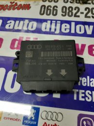
Retrofitting PDC (Park Distance Control) + PLA (Park Lane Assist)

I'd get some second hand genuine ones from eBay. At least you have verified it as working though

Sent from my SM-G950F using Tapatalk

I've got a refund of the broken ones and the seller proposed shipping me four new ones. Now I know the wiring is OK I agreed, so first check if those will work and if not I'll get some genuine ones yep :).

Final version (4.0) of the guide up now. Will host it for a few months, when down please contact me.
CLICK

https://drive.google.com/file/d/11XVVfBClUtR63sM-WRpo2ffOPUdEWXgY/view?usp=sharing
 
Does anyone know, is it possible to use other model of PLA module, for example, from Audi A4 or from similar cars, like VW Golf MK6.

Audi A3 8P with PLA (or even with 8K module) are very rare, and hard to find
 
I used this site to buy the control module and some other staff (module bracket, buttons)
Postage to Greece was 25€. Not terrible, not great.
So if you are located in Europe, you can use this site.
https://www.bm-parts.nl/
You need 8P0919475J or E Or K or P.
I did a quick search and there is available 3 out of 4 versions.

I have no idea if you can use the module of different car.
 
Does anyone know, is it possible to use other model of PLA module, for example, from Audi A4 or from similar cars, like VW Golf MK6.

Audi A3 8P with PLA (or even with 8K module) are very rare, and hard to find

eBay is your friend :D.
Look at the German eBay, eBay kleinanzagen, lot's of extra's there. It's after all, a German product :).

https://www.ebay-kleinanzeigen.de/
 
I used this site to buy the control module and some other staff (module bracket, buttons)
Postage to Greece was 25€. Not terrible, not great.
So if you are located in Europe, you can use this site.
https://www.bm-parts.nl/
You need 8P0919475J or E Or K or P.
I did a quick search and there is available 3 out of 4 versions.

I have no idea if you can use the module of different car.

Even the shipping inside NL isn't great. I pay €10,- and when I go to a pick-up point and send it myself it's €7,25.
BM-Parts is a company so they even have a contract with PostNL (they pick it up from their company) and they can send packages for around €3,-. So they earn alot of money with sending alone.. But everybody does it, so why not right.
 
Small update on my PLA mod:

I got the four appropriate sensors in now. Will be testing them on saturday cause it's ******* 36 degrees out here the whole week.

Sad thing is, my system doesn't work anymore now. For some reason one of my sensors is giving a short to ground (just like the last time). If it's the left sensor again I think I need to rewire the PLA sensors since they are connected with some Chinese copper cables now and I don't really trust them 100%.

Weird thing is that it works for a couple of days and then quits which makes me thing the wires are ok.....
 
Thank everyone for help.
But I manage to find appropriate one, model "K", on scrapyard in town near me, €40, with postage. Already bought front bumper wiring and 4 sensors. Sensors on back bumper are factory fitted. Now to collect other parts, and then to work.
Wish me luck!
 

Attachments

  • 176796661_5f2aa2d228fe2.jpg
    176796661_5f2aa2d228fe2.jpg
    176.9 KB · Views: 357
  • Like
Reactions: henkkeumus and George Kost
Thank everyone for help.
But I manage to find appropriate one, model "K", on scrapyard in town near me, €40, with postage. Already bought front bumper wiring and 4 sensors. Sensors on back bumper are factory fitted. Now to collect other parts, and then to work.
Wish me luck!

That's a GEN1.5 module. Good luck :)
 
Made the decision I'm going to wire the PLA sensors again. I don't fully trust the chinese wires because when a new sensor is inserted the system works again...
 
Great and informative guide! Thanks for sharing every single step.

I’ve been primarily researching to do PDC only (8P 2006) and deciding between rear only or rear and front. As my rear bumper is from facelift model with sensors already in I thought the easiest and laziest way is to go with rears for now. Could anyone weigh in on the following questions that I have:

1. I’ve found control module with interchangable part numbers 8k and 8p, any foreseeable issues on A3 8p? Would anyone have a clear guide of last letter/mod option and which are suitable? The one I am looking at is 8P0919475M I know common one is ending with G for the 4 channel one.


10620459_572397ab-25ea-44b4-bd40-452b6121c587.jpg


2. As I am basing it on facelift module/sensors would button function properly to switch on/off rear senors? From wiring in elsa it seems it should but I haven’t tried it in a flesh.


Thanks in advance for any feedback!
 
1. I am not sure if this module is right for you. Maybe someone else knows.
As for the module, for the facelift model, you can see this link. Link
You are looking for PR-7X1 (rear PDC only). So F, M or G.
2. For rear PDC only, there is no button on the dash.
 
Thanks for quick reply.

It lists M so I suppose it should be fine, upon checking elsa 8K wiring is the same as 8P for module wiring on T16f and T12i connectors.

Right, I am aware that there isn’t a switch from the factory though as it connects to T16f connector it should be similar if not the same as 8 channel module whcih does come with one. Only reason I am intersted in it is to have an actual option to turn it on/off.
Is hitting the witch turns parking sensors off (default being always on when in reverse) or turns it on?
 
For the front and rear PDC (7X2), the button enables the front sensors.

I have not started the retrofit yet so @henkkeumus am I right?
 
  • Like
Reactions: karx
For the front and rear PDC (7X2), the button enables the front sensors.

I have not started the retrofit yet so @henkkeumus am I right?

Hiya bud I can weigh in if you like. Sorry guys I’m back to work now so I’ve not had much chance to catch up on the forum. I can confirm though that the pdc button will activate all the pdc sensors so front and rear. Putting the vehicle into reverse also activates them obviously but if you don’t want them on you can press the button and turn them off also.

I will say it’s handy having the button if you’re pulling into or out of a tight space and haven’t yet selected reverse ie you want to just drive straight out but want to make sure you don’t clip anything. It also comes in handy when pulling up on a drive. I use it a lot after a night shift when I get home and am going slow enough I tap the button and use it to make sure I don’t hit the mrs car haha.

Hope this helps works dying down now so I’ll be available abit more if anyone needs any help. Though on my 2004 I just went straight to 7X5 but I’m pretty sure 7X2 has the on/off button installed. I know 7X1 didn’t.


Sent from my iPhone using Tapatalk
 
And for the second time the system "failed" giving me a Short to ground to a Parkingaid sensor and lower limit exceeded error.
I've let it rest for a while because it was the 2nd time already.

Yesterday I got the frondend off and did some tests.

1. When I use my old parking aid module and only connect the rear PDC it works OK. This means the rear PDC can be excluded from the problem.
2. When I use the PLA parking aid module and remove the PLA sensors from the loom completely the system works for a few seconds and then throws an error about missing the PLA sensor signals. This means I can exclude the 4 front PDC from the problem.
3. With the help from Troubs12 I did some continuity test. Measuring PIN 1 to PIN 1 (live) and PIN 3 to PIN 3 (ground) on the sensor connectors. Found a flaw in my wiring, I switched ground and live on a PLA sensorconnector. I switched those and hoped for the best. Unfortunate same error(s).

Let the problem rest and going in for it again today. I used AliExpress prewired connectors and want to get those out to be 100% sure it's OK now. So I'm going to make new connectors, hardwire them to test it. If that still gives an issue I think my module is bad.

- Voltage on PINS is OK. (12V)
- Continuity tests are OK.
- Front and rear PDC are OK.
- Problem is something with the PLA splicing into the loom or the signal from the sensors ain't coming through so it think's a sensor is shorted to ground.

I'll update tonight.
 
Aaaaaaand nothing... bugs me that it worked before, failed two times now and cant get it to work again.

Luckily [mention]Troubs12 [/mention] to the rescue, sending over my loom to him to check on a working car and PLA system. Cant thank him enough

And cant wait for the loom and fit finally to be done pfffffft.
 
Sorry to hear that you still facing problems.
Hope you and Troubs12 sort it out soon.

Is there any possibility that the problem might be at the two signal cables that go from the module to the sensors?
Did you use good quality cables?
 
Sorry to hear that you still facing problems.
Hope you and Troubs12 sort it out soon.

Is there any possibility that the problem might be at the two signal cables that go from the module to the sensors?
Did you use good quality cables?

Well I used the PDC loom from Kufactec. When I disconnect and remove the PLA from the Kufatec loom entirely it gives me a optical PDC on screen for 3 seconds and then throws an error about the missing PLA.

This means that the PDC system is working 100% and is OK. There is something to do with the PLA sensors/ wiring. Well I used 1mm wires and when I see the kufatec loom they used 0,3 or 0,5mm wires. I spliced the PLA power and ground right before the PDC sensors so my thought could be that the PLA sensor draw to much current away from the PDC sensor. The wires I use are thicker then the PDC wires and thuss the current flows to the PLA sensors and won't reach the PDC causing the system to throw the "lower limit exceeded" and "open or short to ground parking aid sensor" errors.

I then tested the theory by giving my PLA sensors a seperate 12v power feed. This removed the errors and gave me a "short to plus" error. This is the point where I had no clue anymore and couldn't be bothered to search deeper, I had the frontend off the whole weekend and wasn't getting any further.

Then Troubs12 and I brought up the idea that I sent him the loom so he can take a proper look and test it on a working car with a known good setup. This way it would be plug and play for me once it returned. I'm really curious what the "problem" could be, I honestly think this was/ is the problem but I didn't solved on the appropriate manner.

So, when the loom comes back and worked on Troubs12 his car I know my module is at fault and maybe did all the cutting, splicing and troubleshooting for nothing. But lets hope it finally gets resolved lol :D
 
  • Like
Reactions: Troubs12 and George Kost
Well I used the PDC loom from Kufactec. When I disconnect and remove the PLA from the Kufatec loom entirely it gives me a optical PDC on screen for 3 seconds and then throws an error about the missing PLA.

This means that the PDC system is working 100% and is OK. There is something to do with the PLA sensors/ wiring. Well I used 1mm wires and when I see the kufatec loom they used 0,3 or 0,5mm wires. I spliced the PLA power and ground right before the PDC sensors so my thought could be that the PLA sensor draw to much current away from the PDC sensor. The wires I use are thicker then the PDC wires and thuss the current flows to the PLA sensors and won't reach the PDC causing the system to throw the "lower limit exceeded" and "open or short to ground parking aid sensor" errors.

I then tested the theory by giving my PLA sensors a seperate 12v power feed. This removed the errors and gave me a "short to plus" error. This is the point where I had no clue anymore and couldn't be bothered to search deeper, I had the frontend off the whole weekend and wasn't getting any further.

Then Troubs12 and I brought up the idea that I sent him the loom so he can take a proper look and test it on a working car with a known good setup. This way it would be plug and play for me once it returned. I'm really curious what the "problem" could be, I honestly think this was/ is the problem but I didn't solved on the appropriate manner.

So, when the loom comes back and worked on Troubs12 his car I know my module is at fault and maybe did all the cutting, splicing and troubleshooting for nothing. But lets hope it finally gets resolved lol :D

Got the loom the work begins hahaha. It looks like kufatec have wired it wrong however as the ops worked I might have to send you some repin instructions for you to do on your car so it’s wired like the diagram but it shouldn’t take long. Once I get the suspension stuff done I’ll fit the loom to mine to be 100% it’s all good before sending back.


Sent from my iPhone using Tapatalk
 
  • Like
Reactions: henkkeumus
Got the loom the work begins hahaha. It looks like kufatec have wired it wrong however as the ops worked I might have to send you some repin instructions for you to do on your car so it’s wired like the diagram but it shouldn’t take long. Once I get the suspension stuff done I’ll fit the loom to mine to be 100% it’s all good before sending back.


Sent from my iPhone using Tapatalk

Imma sent them a refund letter when they ****** it up lol. I've almost ruined the loom because they delivered me a "wrong" loom.
 
Troubs12 what is it wrong with the loom?
There also was a wrong pin regarding one of the buttons!
 
Kufatec are synonymous for wiring looms wrong, I don't use them for years due to this & generally make them myself, they cause so many issues & the support years ago when I last used them was awful, shame it's not changed.
 
  • Like
Reactions: henkkeumus and George Kost
Update:

Can't thank @Troubs12 enough for the effort he is going through for me.
He just rewired the loom and tested it on his car, big suprise, it didnt work.

photo-2020-09-01-18-54-01.jpg


photo-2020-09-01-18-54-05.jpg


photo-2020-09-01-18-54-07.jpg


He told me he was holding Elsa next to him as a reference but the pins weren't adding up in the engine compartment connector. The pins at the ECU were pinned correctly but the pins in the connector were just put in at a random place making no sense or reference to ElsaWin.

For example;

ElsaWin
ECU pin 5
Bumper pin 3
Front left sensor

Kufatec
ECU pin 5
Bumper pin 2
Front left sensor

Took myself a while before I get it but I'm happy he got around it. This means he just need to move a few pins and it should be a go for the loom :). Happy and very pleased he is willing to do all these things for me, I know for a fact without him it would take me after 2021 before I finished this mod lol :D
 
Just finished it’s all done though I need to dig you out some new pla sensors I’ve found one and then robbed one from my car but I kinda need that one haha. You’ll have some re pinning to do but I’ll send you everything you need


Sent from my iPhone using Tapatalk
 
  • Like
Reactions: henkkeumus
So the problem is with the Kufatec loom that goes to the front sensors?
This would give you wrong signal from each sensor. For example, front left instead front right. But this should mess up only the OPS on the head unit.
since the two signals for the PLA are new cables that you added, you shouldn’t have error in the PLA part of the retrofit.
I hope I am wrong and he can sort all your problems out!
 
Too be honest I just de pinned and started again once I got the looms sorted I had the mrs walk around the car so I could see the display change then disconnected the left pla sensor and it logged a fault with the left so I think we’re finally out of the woods.

Though I did have to repin my main loom as it was a kufatec one and was wrong from day one but as I only added in the pla I didn’t realise till I was sorting out this one haha.


Sent from my iPhone using Tapatalk
 
  • Like
Reactions: George Kost
Kufatec are xxxxs tbh
 
  • Like
Reactions: George Kost
I know man but too be fair they are cheap and I priced up all the connectors, pin ends, seals and wire etc and they were cheaper i definitely should have checked the pins were going to the right place. Also sorry man I haven’t had a chance to listen to your message yet. It’s been manic in work and I’ve not had 5 minutes lol. I’ll email that info over tonight though


Sent from my iPhone using Tapatalk
 
  • Like
Reactions: NHN
So the problem is with the Kufatec loom that goes to the front sensors?
This would give you wrong signal from each sensor. For example, front left instead front right. But this should mess up only the OPS on the head unit.
since the two signals for the PLA are new cables that you added, you shouldn’t have error in the PLA part of the retrofit.
I hope I am wrong and he can sort all your problems out!

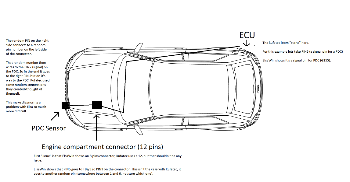
The pins at the ECU are OK, but the go to a random pin in the connector in the engine compartment. Then again we have some random pins connecting and those correspond to the PDC pins as Elsa shows it.

Bit hard to explain, it had me for a while but when you get it it makes much more sense lol.
Tried to visualize it for you, this is what you mean, right? @Troubs12

c41b938191efda2dc49d5fc8d54e1ee8.png
 
  • Like
Reactions: George Kost
Not to mention that they also forgot or did some wrong imprints on the internal loom already. They switched the connections for the buttons.. I firstly doubt myself but now I see this I'm kinda sure it wasn't me lol.
 
  • Like
Reactions: Troubs12
Yeah that’s it basically it goes:

Ecu correct pin.

Middle connector same random pin both sides

Sensor correct pin


Sent from my iPhone using Tapatalk
 
It’s all done now though that’s the main thing. I’ll dig out that other spare sensor tomorrow and if you’re very very lucky I might even have some paint lol


Sent from my iPhone using Tapatalk
 
  • Like
Reactions: Andreashadji
Got the loom back from Troubs :)
Will fit this weekend, just need to do some repinning because the loom is now Audi OEM pinned and not Kufatec pinned.

12pins on the module to the connector in the enginecompartment:
Pin 1 ecu goes to pin 1 on the bumper
Pin 2 ecu goes to pin 2 on the bumper
Pin 5 ecu goes to pin 3 on the bumper
Pin 6 ecu goes to pin 4 on the bumper
Pin 7 ecu goes to pin 5 on the bumper
Pin 8 ecu goes to pin 6 on the bumper
 
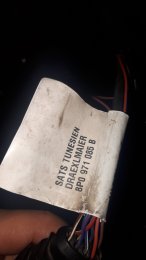
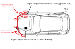
I have small issue with wiring. My front bumper wiring is Audi genuine, 8p0 971 085B, from scrapyard, not Kufatec. I added 2 extra connectors for PLA sensors.
But according to original wiring diagram and pin-outs, this genuine wiring must go from right to left side of bumper (8-pin connector must be on right side of bumper).
Does anyone know how factory fitted front sensors wiring enter from cabin to engine? Is there any holes in foot area on front passenger side?
Is it easier to enter to engine compartment from right side and keep original wiring pin-out,
or to do repining on ECU wiring?
 

Attachments

  • 20200920_095401.jpg
    20200920_095401.jpg
    1 MB · Views: 318
  • c41b938191efda2dc49d5fc8d54e1ee8.png
    c41b938191efda2dc49d5fc8d54e1ee8.png
    89.1 KB · Views: 299
Last edited:
I have small issue with wiring. My front bumper wiring is Audi genuine, 8p0 971 085B, from scrapyard, not Kufatec. I added 2 extra connectors for PLA sensors.
But according to original wiring diagram and pin-outs, this genuine wiring must go from right to left side of bumper (8-pin connector must be on right side of bumper).
Does anyone know how factory fitted front sensors wiring enter from cabin to engine? Is there any holes in foot area on front passenger side?
Is it easier to enter to engine compartment from right side and keep original wiring pin-out,
or to do repining on ECU wiring?

Side doesn't really matter if you have the PDC's already fitted. You only need to feed 2 signal wires to your module then. Just follow the loom, I'm not sure where it enters the cabin from the left side though.
 
For sure side doesn’t really matters.
The only problem I see, is that it would show the wrong sensor in the OPS if you have the RNS-E if the sensors are wrongly connected.
You can always re-pin the connector so you have the correct signal to the correct pin of the module.
Now in the left side of the car, for LHD cars, there is a hole in the firewall just behind the steering wheel that lead just behind the battery in the engine bay.