

Audi A3 8P parking sensor retrofit
- Thread starter Igoaam
- Start date
You are using an out of date browser. It may not display this or other websites correctly.
You should upgrade or use an alternative browser.
You should upgrade or use an alternative browser.
The sound trick works on any sensor that gets power. Any car.
Check this at 3:15
View: https://youtu.be/0dooytSUOnc?si=8rPGSD9r_IKT6o2x
I also got mine from AliExpress. One of them got burned really fast and bought second had originals from eBay as well.
i tried this and theres no sound coming from the front or back. So what does this mean?
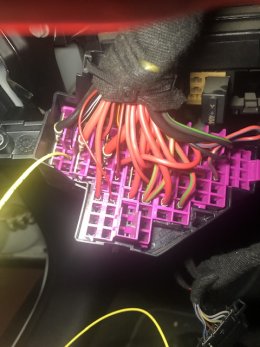
Yh i used that same slot. You know how the other slots have two wires how comes that one only has one wire?Fuse slot 5 is the one I used too.
First row. See the yellow cable.
Check with the multimeter if there is 12v with the ignition off or not.
I wasnt sure how to check if theres 12v on the fuse when the ignition is off So i tried checking the slot with the multimeter, i put it on 20 volts on the multimeter and put my two probes into the fuse slot and it came back with zero. Unless im doing it wrong then please let me know how to do this step.
You need to put one probe in the use and the negative probe on an earth
Both fuse pins will be at 12v if there is a fuse connected
It sounds to me like a wiring fault to the sensors. What sensors are they? Anything from AliExpress raises red flags for me as who knows what it is
To be honest used genuine sensors would be my recommendation. The front and rear sensors are so plentiful due to being common across VAG. The side PLA ones are not as common
Does each sensor have 12v going to it (tested with multimeter)?

Ok i will try that. And do i set the multi meter to 20V? And this is with ignition on or off?You need to put one probe in the use and the negative probe on an earth
Both fuse pins will be at 12v if there is a fuse connected
It sounds to me like a wiring fault to the sensors. What sensors are they? Anything from AliExpress raises red flags for me as who knows what it is
To be honest used genuine sensors would be my recommendation. The front and rear sensors are so plentiful due to being common across VAG. The side PLA ones are not as common
Does each sensor have 12v going to it (tested with multimeter)?
Ive checked my wiring doing a continuity test and they all seem to be fine. But i will check again. And check the pin locations. Is there anything else i can do to check my looms are ok apart from continuity. Only thing was when making the looms i used 0.5mm2 wires instead of 0.35mm2 which is what i saw later on the wiring diagrams. And my parking sensor looms i bought some used ones from ebay and rewired it and added pla wires. So there could be a mix of 0.35 and 0.5mm2 wires. Would that cause any issues?
Yh all my sensors are from aliexpress. I have recently bought some oem sensors from ebay they should arrive soon and i will swap them out. I havent bought oem pla ones as they are bit more expensive and im hoping they are ok if not then il buy some later.
Is there any way to check if the pdc+pla module is faulty?
Im not sure if 12v is going to sensors. How can i check? Sorry ive never used multimeter before doing this retrofit. Please advise me of the steps and what setting to put it on. Thank you
If you set the multimeter to 20v, then it will count up to 20. So you are ok. If tor example you would want to measure something 50v, then you should change the dial to higher voltage. Some multimeters are AUTO. Anyway.
Each sensor has 3 cables.
12v power (pin 1), signal (pin 2), ground/earth(pin 3).
So if you test with the multimeter at pins 1 and 3 the connectors, there should be 12v from the module.
You don't have problem with the difference in 0.35mm2 and 0.5mm2.
Also check the connector of the module, the T16 connector. Where power comes to the module.
Check if you measure 12v at pins 1 and 8.
Thanks i will give that a go once im back, im just away for the weekend. I will let you know what the results are.If you set the multimeter to 20v, then it will count up to 20. So you are ok. If tor example you would want to measure something 50v, then you should change the dial to higher voltage. Some multimeters are AUTO. Anyway.
Each sensor has 3 cables.
12v power (pin 1), signal (pin 2), ground/earth(pin 3).
So if you test with the multimeter at pins 1 and 3 the connectors, there should be 12v from the module.
You don't have problem with the difference in 0.35mm2 and 0.5mm2.
Also check the connector of the module, the T16 connector. Where power comes to the module.
Check if you measure 12v at pins 1 and 8.

So i havent had a chance to check the parking sensors cables yet but i have checked the t16 connector on pin 1 and 8 and i got a reading which kept fluctuating from -13.88 to -13.93. Is this ok? Should it be negative? I have attached a pic. I will check the parking sensors connectors tomorrow.If you set the multimeter to 20v, then it will count up to 20. So you are ok. If tor example you would want to measure something 50v, then you should change the dial to higher voltage. Some multimeters are AUTO. Anyway.
Each sensor has 3 cables.
12v power (pin 1), signal (pin 2), ground/earth(pin 3).
So if you test with the multimeter at pins 1 and 3 the connectors, there should be 12v from the module.
You don't have problem with the difference in 0.35mm2 and 0.5mm2.
Also check the connector of the module, the T16 connector. Where power comes to the module.
Check if you measure 12v at pins 1 and 8.
Attachments
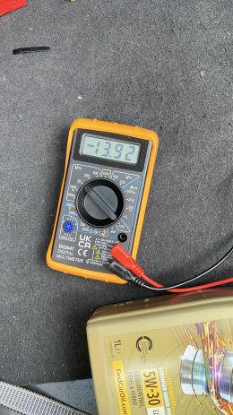
Negative means you have the positive probe on the negative cable/earth
Fluctuating around that voltage is normal when the alternator is charging the battery. I assume you had the engine running at the time?
Fluctuating around that voltage is normal when the alternator is charging the battery. I assume you had the engine running at the time?
Yh i probably did have the cables wrong way my bad. And yes i had the engine running, should i test it with just ignition on?Negative means you have the positive probe on the negative cable/earth
Fluctuating around that voltage is normal when the alternator is charging the battery. I assume you had the engine running at the time?
Ok thats good. I will check the connectors of the parking sensor looms tomorrow. Is there any way i can check the parking sensors itself with the multimeter to see if they are faulty or not?No that's fine, if it has power with it running it will have power with ignition only also but closer to the 12 volts region

Not that I know of. Just check the pos and neg of each preferably while connected. If you get approx 12v at the right pins then the wiring is ok. I say while connected as many electrics in these cars self check and there's a chance the power would be cut off if it detects open circuit
And if you have power to the connectors of the sensors, do the audio test with your phone as well!
It is a bit tricky to position the mic at the sensor but you will understand when you do it!
It is a bit tricky to position the mic at the sensor but you will understand when you do it!
I'm not sure what measuring blocks the PDC module has but might be worth having a look. It might have each sensor individually listed. I don't have PLA on my TT, only 8 sensors, but I have a MK6 Golf with factory fitted PLA I could compare with
On vcds you can see all 10 sensors on measuring blocks.I'm not sure what measuring blocks the PDC module has but might be worth having a look. It might have each sensor individually listed. I don't have PLA on my TT, only 8 sensors, but I have a MK6 Golf with factory fitted PLA I could compare with
Not sure in this case where the system does not work yet!
You should add PLA! Your TT is almost an A3!!
")
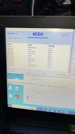
I can see all 10 sensors on the vcds, does this mean its powered on? See attached.On vcds you can see all 10 sensors on measuring blocks.
Not sure in this case where the system does not work yet!
You should add PLA! Your TT is almost an A3!!
Ive already tried to do that before it didnt work so if there is actual power going to the connectors then it must be a faulty sensor?And if you have power to the connectors of the sensors, do the audio test with your phone as well!
It is a bit tricky to position the mic at the sensor but you will understand when you do it!
Attachments


You should add PLA! Your TT is almost an A3!!
I plan to but I need to change the steering rack for it!
I can see all 10 sensors on the vcds, does this mean its powered on?
Do those figures change when there are objects in the way?
255 sounds very coincidentally like the max value of a byte so wondering if it's just defaulting to that if there's an issue
On vcds you can see all 10 sensors on measuring blocks.
Not sure in this case where the system does not work yet!
You should add PLA! Your TT is almost an A3!!
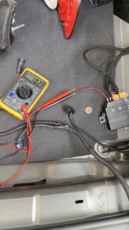
So ive checked each rear parking sensor loom connectors and they are all showing as 1.0v so as they were all showing the same i thought id checked the module connector T12i and check pin 8 and 11 and it was showing 1.0V aswell. And then i thought let me check pin 1 and 8 of T16f on the module and see what reading i get and it showed 13.0V and i didnt want to take my front bumper for now so i just unplugged the connector in the engine connecting to the front sensor looms and check the pins there and it was reading 13.0v also. So am i right to assume i have a faulty module? And the rear t12i connection is faulty? Is there any way i can repair this?Do those figures change when there are objects in the way?
255 sounds very coincidentally like the max value of a byte so wondering if it's just defaulting to that if there's an issue
Attachments
It doesnt really specify which sensor so i assume its the overall.I'd have to look at the measuring blocks for mine
In your screenshot it says 1.1 volts. Is that for a particular sensor?
And sorry in my last post when i said i checked T16f i meant T12t which is the connector for the front sensor looms. So im getting 13V from the module on connection T12t but on T12i i only get 1.0V from the module.
Attachments

This is for sure a problem.but on T12i i only get 1.0V from the module.
You did a measurement with that loom disconnected correct? Directly on the pins of the module. Pins 8 and 11.
So if you have correct voltage to the module, and the module provides correct voltage to the front loom, but not correct voltage to the back loom, then probably you have a faulty module. Not sure at all if this is fixable. You can take of the cover and see for any visible damage. Maybe corrosion on any pins.
And not sure if it should have 12v voltage to the back when the system is not working.
To the front, there should be always 12v, because it is always scanning the 2 side sensors. Because as soon as you press the PLA button, it shows you the free spot even if you have passed the beginning of it. So I suppose it keeps measuring all the time at least the 2 side sensors.
But then you might should have measurements at the measuring blocks for at least the front sensors. Not that value of 255.
If you can source another module for testing that would be great!
Yes i measured this directly from pins 8 and 11 of the module.This is for sure a problem.
You did a measurement with that loom disconnected correct? Directly on the pins of the module. Pins 8 and 11.
Yh i did take it off but i cant see anything on the board which would be causing this issue.So if you have correct voltage to the module, and the module provides correct voltage to the front loom, but not correct voltage to the back loom, then probably you have a faulty module. Not sure at all if this is fixable. You can take of the cover and see for any visible damage. Maybe corrosion on any pins
The only other thing i could do is swap the sensor with the used oem ones to check if its a sensor issue and then see if there is 12V to the back. Or if someone can check what Volt they get from pins 8 and 11 of their PLA module and see if its similar to mine or not. Otherwise im going to need to get another module but it is very hard to find a another pla module, ive looked around and i cant find any used ones. New ones are £200+, way to expensive! I just have to hope one pops up soon.And not sure if it should have 12v voltage to the back when the system is not working.
To the front, there should be always 12v, because it is always scanning the 2 side sensors. Because as soon as you press the PLA button, it shows you the free spot even if you have passed the beginning of it. So I suppose it keeps measuring all the time at least the 2 side sensors.
But then you might should have measurements at the measuring blocks for at least the front sensors. Not that value of 255.
If you can source another module for testing that would be great!

I have managed to source another pla module to compare and i am getting the same issues and fault codes. So i guess my original module cant be faulty?This is for sure a problem.
You did a measurement with that loom disconnected correct? Directly on the pins of the module. Pins 8 and 11.
So if you have correct voltage to the module, and the module provides correct voltage to the front loom, but not correct voltage to the back loom, then probably you have a faulty module. Not sure at all if this is fixable. You can take of the cover and see for any visible damage. Maybe corrosion on any pins.
And not sure if it should have 12v voltage to the back when the system is not working.
To the front, there should be always 12v, because it is always scanning the 2 side sensors. Because as soon as you press the PLA button, it shows you the free spot even if you have passed the beginning of it. So I suppose it keeps measuring all the time at least the 2 side sensors.
But then you might should have measurements at the measuring blocks for at least the front sensors. Not that value of 255.
If you can source another module for testing that would be great!
I measure pin 11 and 8 on T12i of the new module and its reading 1.0V. So i cant have both modules faulty? What should i do now. Could it be my wiring or shall i change my sensors? Ive purchased used oem ones from ebay so im thinking to swap them after i come back from holiday.
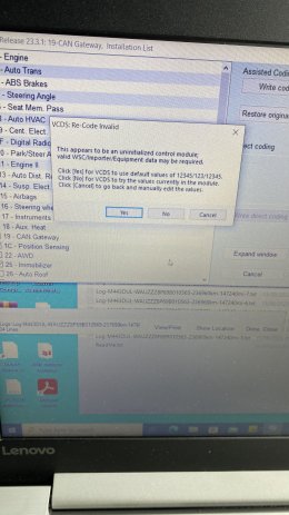
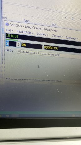
One of the fault codes is incorrectly coded module. Ive changed the coding and i have attached what i selected. Also i get this notification everytime i sepect write code any ideas what i should be selecting? I have attached a pic.
Any help would be appreciated this is realy frustrating me now. Did you manage to check if your module shows 1.0v on T12i? I know it might be bit of a hassle but i would appreciate it. Thank you.
Attachments
-
 IMG_7961.jpeg2.5 MB · Views: 34
 -
 IMG_7962.jpeg1.9 MB · Views: 36
 -
 IMG_7963.jpeg2.2 MB · Views: 37
 -
 IMG_7964.jpeg2.2 MB · Views: 42
 -
 IMG_7964.jpeg2.2 MB · Views: 36
 -
 IMG_7963.jpeg2.2 MB · Views: 36
 -
 IMG_7962.jpeg1.9 MB · Views: 36
 -
 IMG_7961.jpeg2.5 MB · Views: 38
 -
Log-M443DUL-WAUZZZ8P69B010565-237650km-147668mi-1.txt27.4 KB · Views: 41
The uninitialised message must mean you have a brand new module fitted? Or if not there is no harm accepting the VCDS defaults
It is possible the module is cutting power to the sensors because of the fault
I would definitely fit the OEM ones as AliExpress stuff is generally rubbish, and go from there
I am still suspicious of the sensor wiring based on the fault codes
Which canbus are you using for the PDC module?
It is possible the module is cutting power to the sensors because of the fault
I would definitely fit the OEM ones as AliExpress stuff is generally rubbish, and go from there
I am still suspicious of the sensor wiring based on the fault codes
Which canbus are you using for the PDC module?
It is a new module but i also get the same message when im changing the coding on my can gateway.The uninitialised message must mean you have a brand new module fitted? Or if not there is no harm accepting the VCDS defaults
It is possible the module is cutting power to the sensors because of the fault
I would definitely fit the OEM ones as AliExpress stuff is generally rubbish, and go from there
I am still suspicious of the sensor wiring based on the fault codes
Which canbus are you using for the PDC module?
Im not sure about the sensor wiring i did check it with the multimeter but if module itself is giving out 1 V then the sensors should get 1V so i dont think it will be the sensor wires. Or Are you talking about T16f loom? If the T16f powers both connectors T12i and T12t and if T12t is recieving 12V then shouldnt T12i i also recieve 12V? Not sure if i made sense there.
What do you mean by which can bus am i using for pdc module? Which wires? Pin 6 and 16 on the can bus. T16f/6 to Pin 16 and T16f/15 to pin 6.
The canbus wiring sounds correct
Well I'd say swap the sensors and then go from there. The fault codes indicate an electrical fault, which is either the wiring or the sensors
You've checked the wiring so really it only leaves the sensors
Well I'd say swap the sensors and then go from there. The fault codes indicate an electrical fault, which is either the wiring or the sensors
You've checked the wiring so really it only leaves the sensors
Sorry ive been busy and havent had a chance to swap my sensors for the used oem ones. I ended up replacing both front and back. I havent changed the PLA sensors yet but i have ordered some as i cant be asked to rely on the aliexpress ones as im sure theyll fail sooner or later.The canbus wiring sounds correct
Well I'd say swap the sensors and then go from there. The fault codes indicate an electrical fault, which is either the wiring or the sensors
You've checked the wiring so really it only leaves the sensors
Also i decided to recheck my wiring with the multimeter and did a continuity test for all pins and found one of my canbus wire failed the test but im sure when i checked it before it was fine but i ended up replacing that wire. So i clear all the codes and now i only get one fault code for the park assist which is
01316 - ABS Control Module
013 - Check DTC Memory
Ive checked ross tech website what this means and they say theres fault codes stored in the module and to clear/correct it. But i dont have no fault codes on my abs module. Unless there is and theres another way of accessing it. If there is no fault code then do you need a specific abs module for the park assist to work?
So i still get the same long beep with my pdc button flashing, my pla button is unresponsive. I get no optical display on my rnse. I did run an output test and my pla button flashes so i guess there is power going to it.
I have attached my scan please take a look and let me know what i can do to get this to work. I feel like we are finally getting close to solving this . Thanks
Attachments

No i havent, i wasnt aware that was something i had to do. How do i do it? Is there a tickbox or is it some coding i need to change?Have you enabled the adaptation for PLA in your ABS module? Just wondering if that could be the issue
I have downloaded the main guide from @henkkeumus but there was nothing in there about changing the code in the abs module. @George Kost do you know how to do this?I believe the details are in the main guide thread on here. I don't have it in my car ATM