

Hi,
I've bought an ambient lighting kit off aliexpress which contains 4 sub controllers and 1 main controller. I plan to hardwire the 4 controllers into each door.
I've also bought puddle lights(door warning lights) with audi rings and that's not been an issue.
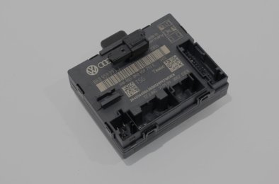
I've recently taken off the door panels for my B8.5 to install puddle lights and ambient strip lights. I have opened the top connector from the DRIVER DOOR CONTROL MODULE ECU B8 8K0959793E.
I have plugged in the puddle lights into pin 16 for positive and 5 for negative for the front doors on the 32 pin connector and 12 and 13 respectively for the back doors on the 16pin connector. However for the ambient lighting I don't know which pin to use as a constant 12v positive terminal when key is in ignition.
I can splice the negative and use the same pins for the puddle lights but I don't know what terminals to use for positive. I've been looking for pin out diagrams for the door control modules but I have not found anything. Pin out diagrams for the front and back door control modules would be great.
I've attached an image of the front door control modules.
Any help would be greatly appreciated.
Thank you
I've bought an ambient lighting kit off aliexpress which contains 4 sub controllers and 1 main controller. I plan to hardwire the 4 controllers into each door.
I've also bought puddle lights(door warning lights) with audi rings and that's not been an issue.
I've recently taken off the door panels for my B8.5 to install puddle lights and ambient strip lights. I have opened the top connector from the DRIVER DOOR CONTROL MODULE ECU B8 8K0959793E.
I have plugged in the puddle lights into pin 16 for positive and 5 for negative for the front doors on the 32 pin connector and 12 and 13 respectively for the back doors on the 16pin connector. However for the ambient lighting I don't know which pin to use as a constant 12v positive terminal when key is in ignition.
I can splice the negative and use the same pins for the puddle lights but I don't know what terminals to use for positive. I've been looking for pin out diagrams for the door control modules but I have not found anything. Pin out diagrams for the front and back door control modules would be great.
I've attached an image of the front door control modules.
Any help would be greatly appreciated.
Thank you
Attachments
Last edited: